Bearing part, heat treatment method thereof, and rolling bearing

a technology of rolling bearings and bearing parts, applied in the field of rolling bearings, can solve the problems of difficult to improve coarse microstructure, etc., and achieve excellent anti-crack strength, increase of aged dimensional change, and long life

Active Publication Date: 2005-09-22
NTN CORP
View PDF69 Cites 27 Cited by
  • Summary
  • Abstract
  • Description
  • Claims
  • Application Information

AI Technical Summary

Benefits of technology

[0008] An object of the present invention is to provide a bearing part having long life against rolling contact fatigue, excellent in anti-crack strength and restricted in an increase of aged dimensional change, a heat treatment method thereof, and a rolling bearing including the bearing part.

Problems solved by technology

However, since the carbonitriding involves diffusion, the bearing part needs to be held at high temperature for a long period of time, which may coarsen the microstructure, making it difficult to improve the anti-crack strength.
Further, there is another problem of an increase of aged dimensional change due to the increased residual austenite.
However, using the alloy steel will increase the raw material cost.
As the environment of use of the bearings has become increasingly severe, future bearing parts will have to be used under the conditions of greater load and higher temperature than in the conventional case.

Method used


Image

  • Bearing part, heat treatment method thereof, and rolling bearing
  • Bearing part, heat treatment method thereof, and rolling bearing
  • Bearing part, heat treatment method thereof, and rolling bearing

Examples


example 1

II. Test Results of Example 1

[0092] (1) Hydrogen Content

[0093] The conventional carbonitrided item having undergone only carbonitriding exhibits very high hydrogen content of 0.72 ppm. This is considered because ammonium (NH3) included in the atmosphere for the carbonitriding decomposed and penetrated into the steel. By comparison, the hydrogen contents of samples B-D are decreased nearly to the half, i.e., 0.37-0.40 ppm, which is at the same level as that of the ordinary quenched item.

[0094] Steel embrittlement attributable to dissolved hydrogen can be alleviated by a decrease of the hydrogen content. That is, with the decreased hydrogen contents, samples B-D of the present example exhibit remarkably improved Charpy impact.

[0095] (2) Grain Size

[0096] In the case where the temperature at secondary quenching is lower than the temperature at carbonitriding (and hence primary quenching), i.e., in the case of samples B-D, extremely fine austenite grains comparable to JIS grain size ...

example 2

[0104] The second example is now explained. A series of tests were performed on materials A, B and C explained below. As a material to be subjected to heat treatment, JIS SUJ2 (including 1.0 wt. % C, 0.25 wt. % Si, 0.4 wt. % Mn, 1.5 wt. % Cr) was employed commonly for A-C materials. Manufacturing histories thereof are as follows.

[0105] A material (Comparative Example): Subjected solely to ordinary quenching (unaccompanied by carbonitriding).

[0106] B material (Comparative Example): Subjected to quenching after carbonitriding (conventional carbonitriding and quenching). Carbonitriding temperature was 845° C. and the holding time was 150 minutes. The atmospheric gas for the carbonitriding was a mixed gas of RX gas and ammonia gas.

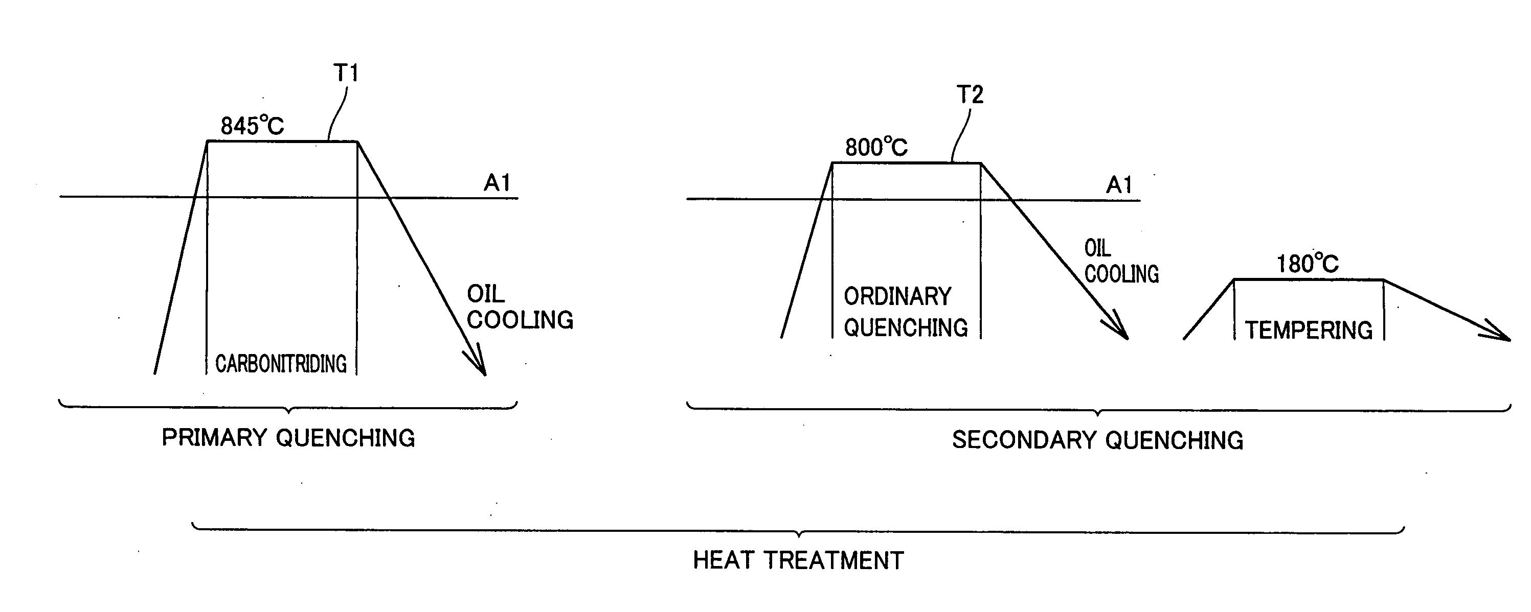
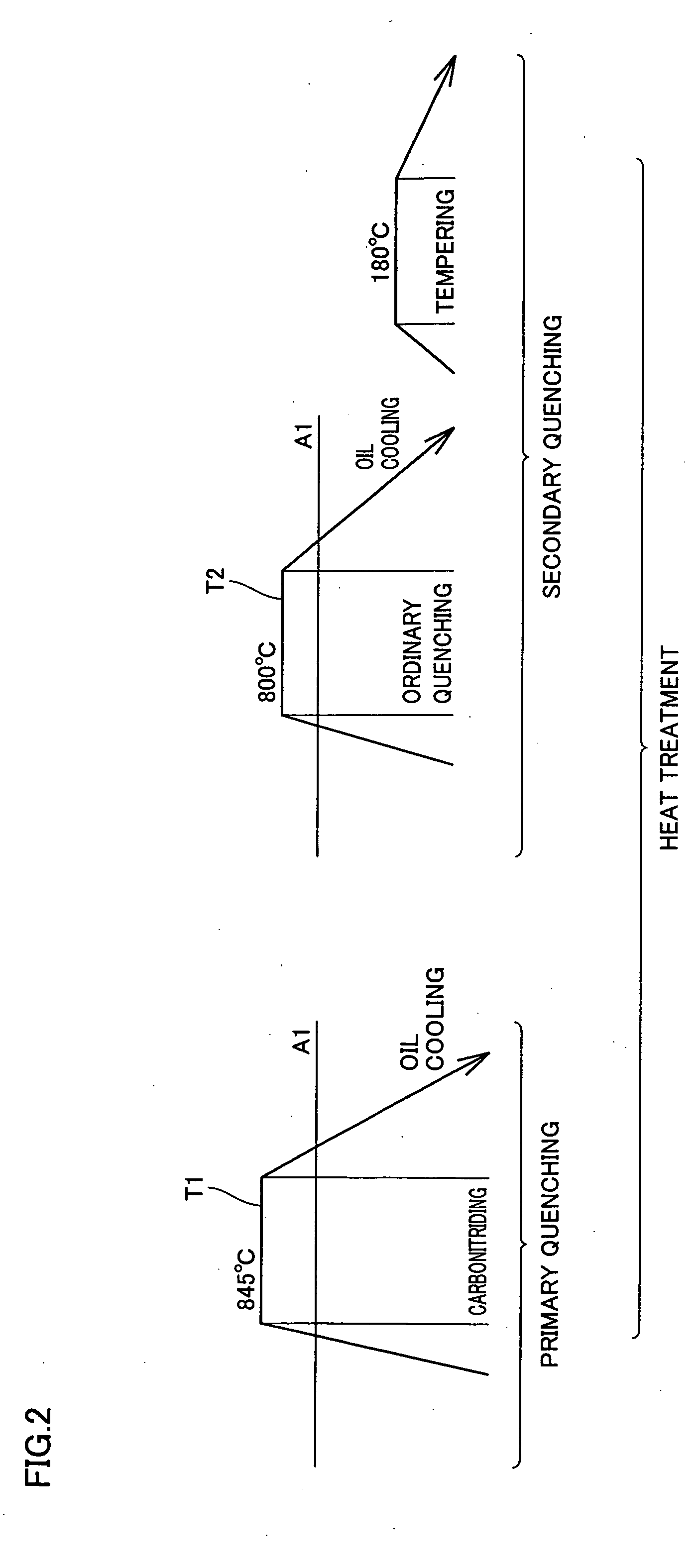
[0107] C material (Example of Present Invention): Bearing steel to which the heat treatment pattern shown in FIG. 2 was applied. It was carbonitrided at 845° C. and held for 150 minutes. A mixed gas of RX gas and ammonia gas was used as the carbonitriding a...


PUM

PropertyMeasurementUnit
temperatureaaaaaaaaaa
mean grain sizeaaaaaaaaaa
grain sizeaaaaaaaaaa

Abstract

A bearing part comprising steel subjected to carbonitriding at a carbonitriding temperature exceeding the A1 transformation temperature, and cooled to a temperature lower than the A1 transformation temperature. The steel is reheated to a temperature for quenching that is not lower than the A1 transformation temperature but lower than the carbonitriding temperature, and then quenched.

Description

BACKGROUND OF THE INVENTION [0001] 1. Field of the Invention [0002] The present invention relates to rolling bearings for use in compressors of automobiles and others, bearing parts used therein, and heat treatment methods thereof. [0003] 2. Description of the Background Art [0004] In one heat treatment method, as a way of ensuring long life of a bearing part against rolling contact fatigue, a surface layer portion of the bearing part is subjected to carbonitriding, with ammonia gas, for example, added to the atmospheric RX gas for heating (disclosed, e.g., in Japanese Patent Laying-Open Nos. 8-4774 and 11-101247). This carbonitriding hardens the surface layer portion, and further generates residual austenite within the microstructure, thereby improving the rolling contact fatigue life. [0005] However, since the carbonitriding involves diffusion, the bearing part needs to be held at high temperature for a long period of time, which may coarsen the microstructure, making it difficult...

Claims


Application Information

Patent Timeline
Patent Type & Authority Applications(United States)
IPC IPC(8): C21D1/18C21D1/78C21D9/36C21D9/40C23C8/32C23C8/80F16C33/30F16C33/62
CPCC21D1/78C21D9/36C21D9/40F16C2240/90C23C8/80F16C33/30F16C33/62C23C8/32F16C19/06F16C33/32F16C2360/44C21D1/18
Inventor OHKI, CHIKARA
Owner NTN CORP
Why Eureka
Try Eureka