[0016] The provision of a single flood gun has clear cost benefits over the use of two separate guns. In addition, the negative and positive beams may readily be ejected coaxially, being focused to respective first and second flood areas of different sizes. This is particularly advantageous when the surface of a sample is non-uniform or rough, since the beams may be directed to the same region of the sample, at the same
angle of incidence. In prior art separate flood gun arrangements, by contrast, some parts of the sample may be shadowed from one or other of the beams, leading to non-uniform charge neutralization of the analysis region. For this reason, it is preferable to
mount the flood gun with its axis as closely as possible to that of the irradiating primary
beam source. The flood gun of the present invention provides a clear
advantage over separate flood gun arrangements in this respect.
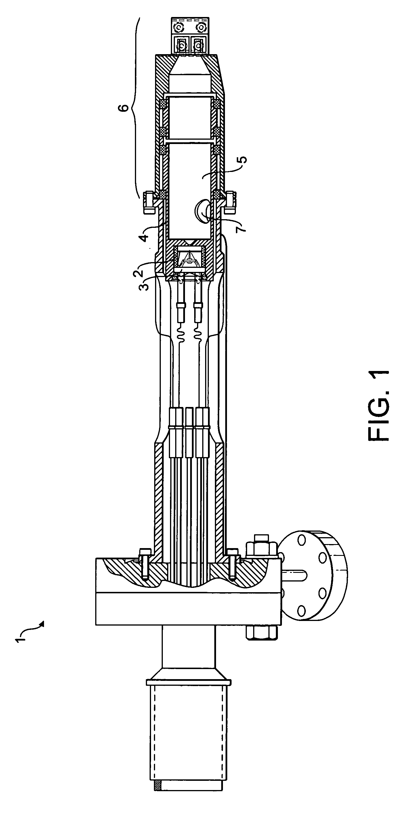
[0017] The flood gun of the present invention is capable of producing beams of low-energy electrons and low-energy positively charged particles, both of which may be focused to respective small spots on a sample, which is not possible with the prior art flood gun 1. In addition, the beam current obtainable with the flood gun for either beam is significantly higher than that available with the flood gun 1. Indeed, by adjusting control signals applied to the extraction and focusing
assembly, it is possible to control the energy and current of the negative beam and positive beam, so that the flood gun may be optimised for any particular application. The flood gun of the present invention is therefore able to provide more effective charge neutralization in comparison with the flood gun 1.
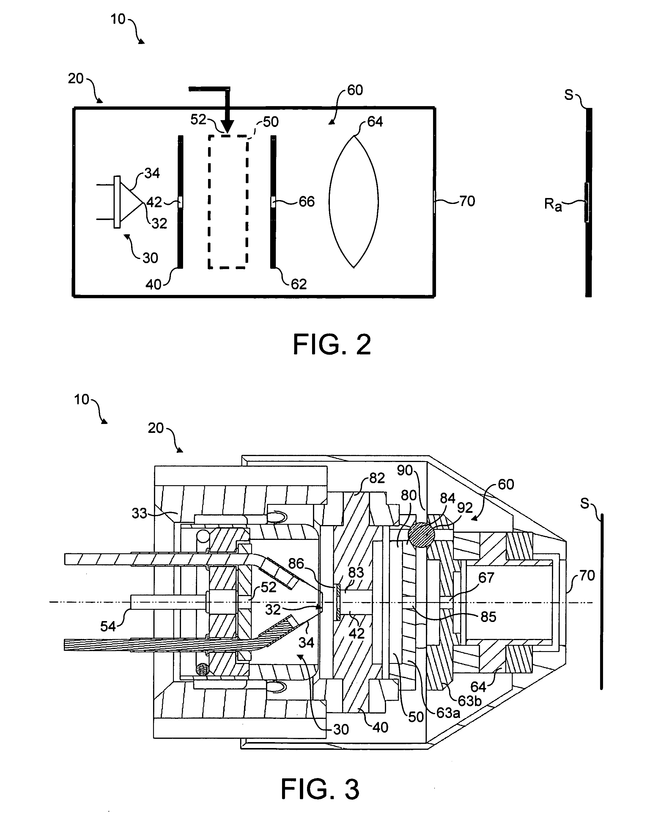
[0018] Preferably, the source of positively charged particles comprises a gas
ionization zone and a
gas supply port, for receiving a supply of an
inert gas within the gas
ionization zone, the gas
ionization zone being arranged to receive therein a supply of
ionizing particles capable of ionizing atoms or molecules of the
inert gas. This offers the ability to provide a higher pressure of gas to be ionized, which in turn results in a greater
ion beam current being obtainable, improving charge neutralizing performance still further. In addition, the overall size of the flood gun may be reduced by the provision of such a dedicated gas ionization zone.
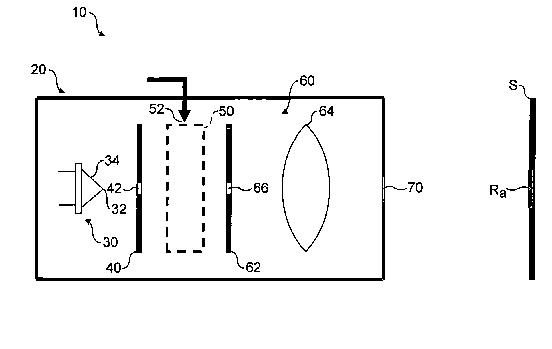
[0019] Preferably, the extraction and focusing
assembly is arranged to extract and focus both the electron beam and the positive
particle beam simultaneously. The flood gun may be readily arranged to produce a focused beam of electrons and a focused beam of positive particles concurrently, in a single mode of operation. That is, once selected, the various components of the flood gun and potentials applied to them may remain unchanged during operation, while providing
focused beams of relatively
high current at the same time. This provides a comparatively simple flood gun.
[0020] Alternatively, the extraction and focusing assembly is arranged to extract and focus the electron beam and the positive particle beam alternately, in an electron beam mode and an
ion beam mode respectively. In this arrangement, the
advantage of greater flexibility is provided, since it is possible to switch or adjust the potentials applied to the various components between
modes. For example, the extraction and focusing assembly may be switched in either mode to accelerate the respective beam. Focusing of a beam under acceleration is preferable under conditions where
space charge effects become limiting, such as with high beam currents. Since it is possible to have complete control over the flood gun parameters in each mode, the benefit of a highly efficient flood gun is offered. The flood gun may be readily optimised to provide a focused negative particle beam and a focused positive particle beam, by switching the parameters between
modes. In particular, significantly larger extraction potentials may be used in the pulsed capacity of the flood gun, one benefit of which is that both ion and electron beam currents may be increased.
[0021] Preferably, the gas ionization zone is a confinement zone, arranged substantially to confine the gas therein. Preferably still, the flood gun further comprises a differential pumping port adapted to be connected to a differential pump for evacuating the flood gun to the second pressure based on a difference between the first
gas pressure generated within the gas ionization zone and a relatively lower, third pressure of an analysis chamber in which the flood gun is employed. In this way, significantly higher gas pressures may be achieved within the gas ionization zone—improving the yield of positive ions generated therein—while limiting the effect of such pressure on other parts of the flood gun and, in turn, on the analysis chamber in which the flood gun is used.

