Motor current reconstruction via DC bus current measurement

Inactive Publication Date: 2005-09-22
INFINEON TECH AMERICAS CORP
View PDF11 Cites 47 Cited by
  • Summary
  • Abstract
  • Description
  • Claims
  • Application Information

AI Technical Summary

Benefits of technology

[0023] In accordance with another aspect of the present invention, current samples taken on the DC bus can be delayed a certain amount of time that is pre-selected to avoid ringing or transients in the motor phase currents that might otherwise provide erroneous results. The time delay can be specifically set so that the motor drive system can calculate the point in the PWM pulse where the sample is taken, so that an estimate of the aver...

Problems solved by technology

The 2-phase modulation reduces the regions where current measurements of the DC bus do not provide accurate motor phase current...

Method used


Image

  • Motor current reconstruction via DC bus current measurement
  • Motor current reconstruction via DC bus current measurement
  • Motor current reconstruction via DC bus current measurement

Examples


Embodiment Construction

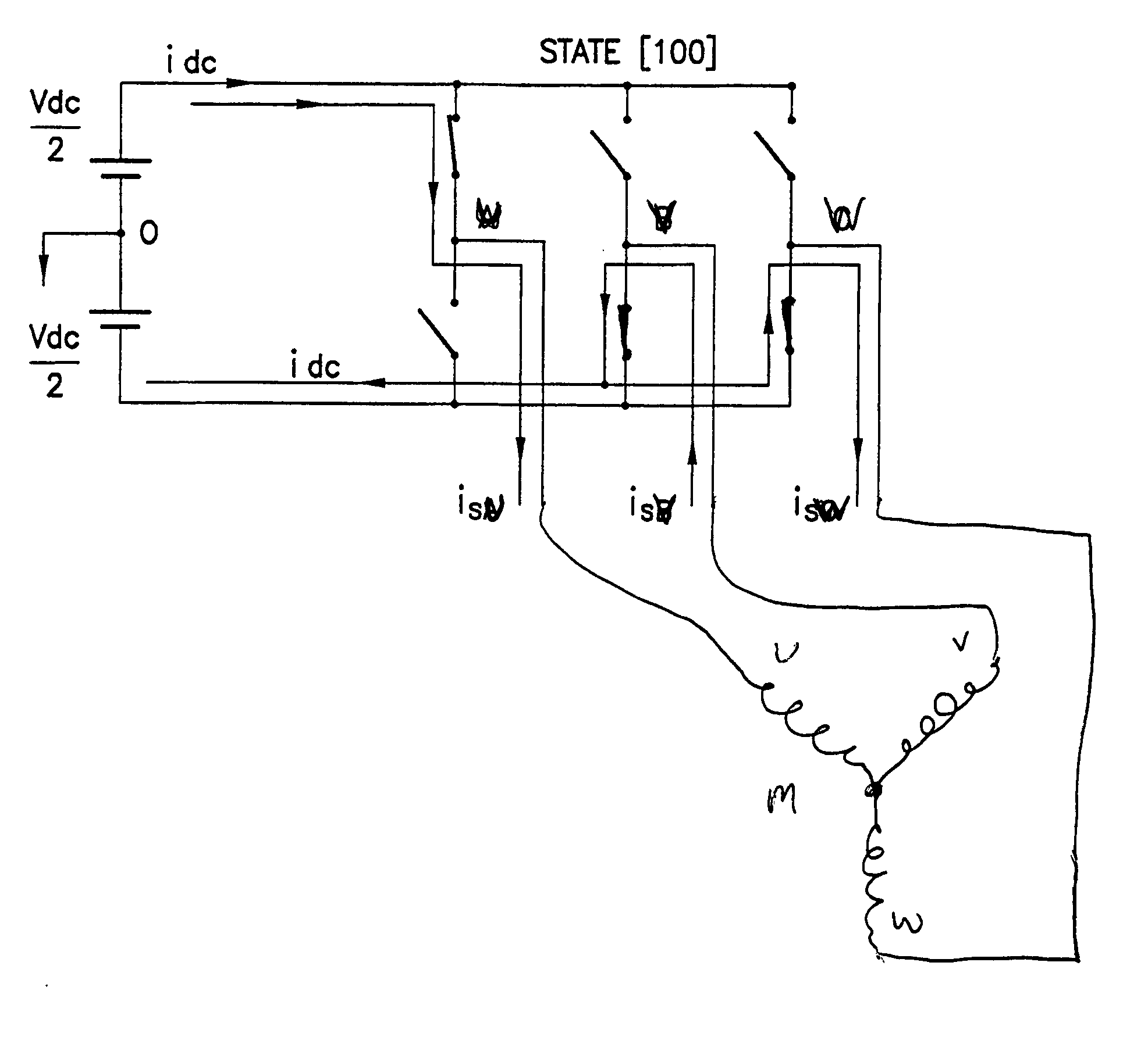
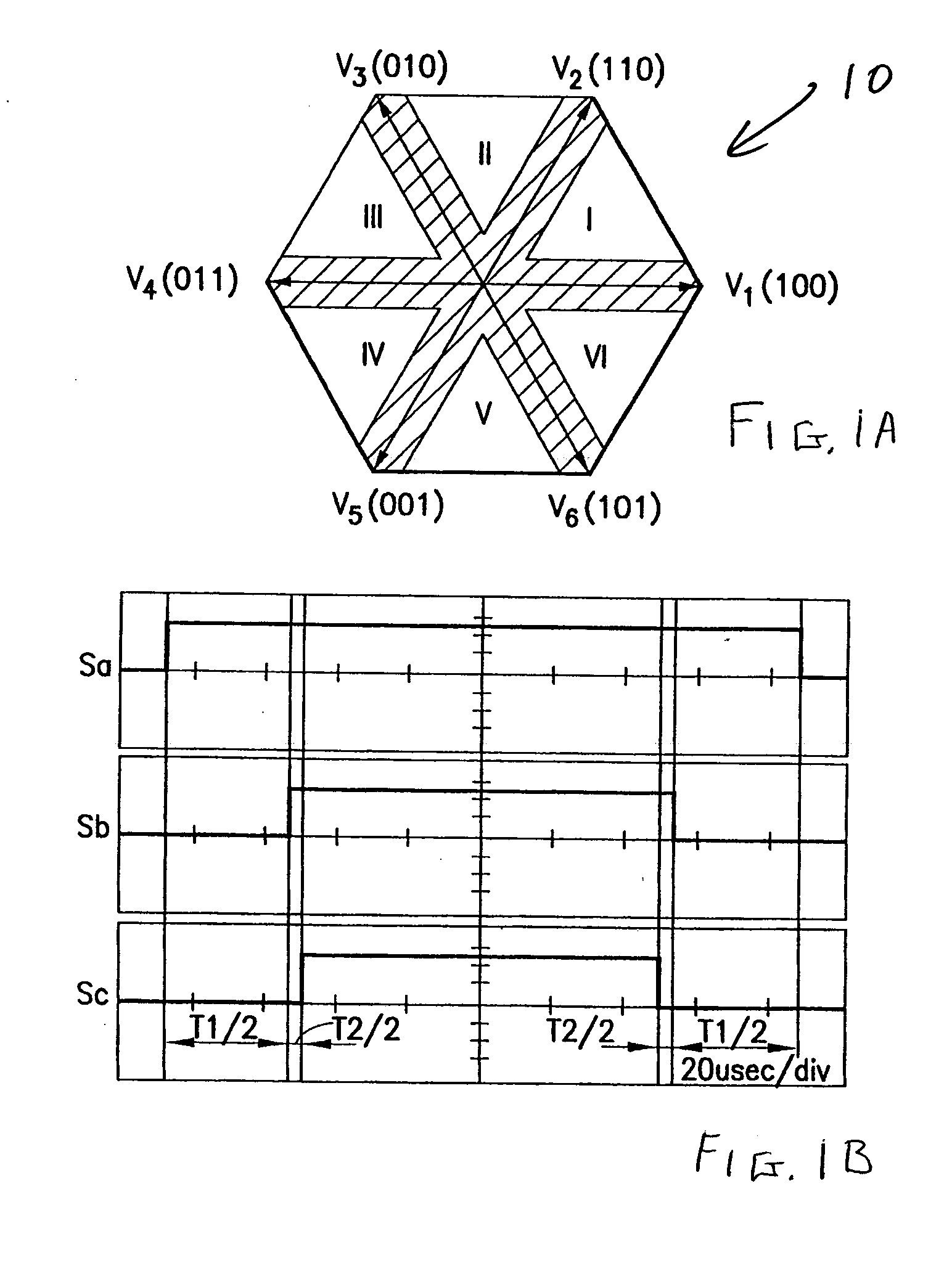
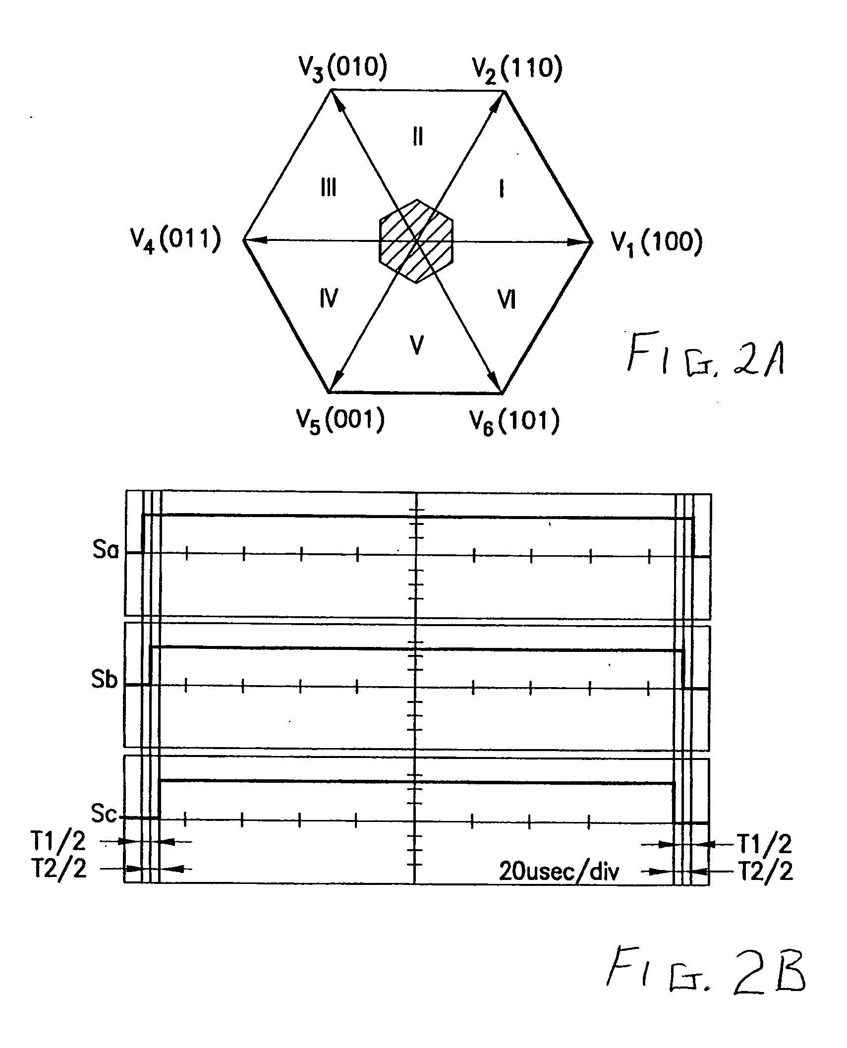
[0042] In a two level PWM inverter drive system, eight possible basic voltage vectors can be produced, including two zero basic voltage vectors 000 and 111. The non-zero basic voltage vectors are represented in the vector diagrams of FIGS. 1A, 2A and 4 and indicate states for a 2-level PWM inverter, such as that illustrated in FIG. 5. In the inverter of FIG. 5, the switches are shown in basic voltage vector state V1, or 100.

[0043] Any desired command voltage vector can be formed by the eight basic voltage vectors. The desired command voltage vector is limited by the maximum output voltage of the inverter, as determined by the DC bus voltage level. In a PWM inverter drive system, motor phase current information can be determined from the DC bus current when non-zero basic vectors are used, such as in the case illustrated in FIG. 5. Each basic vector is assigned a specific time in a PWM cycle to generate a command voltage vector. If the command voltage vector is used only for a very ...


PUM


Abstract

A technique for reconstructing phase currents based on measurements of a DC bus current. Non-observable regions of DC bus current samples to reconstruct phase currents are reduced in size by using two phase space vector modulation. The non-observable regions can be further reduced by omitting deadtime insertions for switch actuations when output current is higher than a given threshold. Voltage command vectors in non-observable areas can be constructed by two time averaged vectors one of which is constructed to obtain an observable DC bus current reflecting motor phase current. The additive vectors have the same combined time average value as that of the voltage command vector in order to preserve volt-seconds. Current samples may also be averaged to provide a more accurate reconstruction of phase current. Current samples are time delayed to avoid transients for more accurate readings. When three phase PWM inverter modulation results in inability to determine the motor phase current from the DC bus measurement, the technique includes dynamically switching to two phase PWM modulation to reduce the time interval when the motor phase current is not determinable through the DC bus current measurement.

Description

RELATED APPLICATION [0001] This application is a continuation-in-part of U.S. patent application Ser. No. 10 / 402,107, filed on Mar. 27, 2003, entitled Motor Current Reconstruction Via DC Bus Current Measurement, which is based on and claims benefit of U.S. Provisional Application No. 60 / 368,860, filed on Mar. 28, 2002, entitled Motor Current Reconstruction Via DC Bus Current Measurement, to each of which a claim of priority is hereby made.BACKGROUND [0002] 1. Field of the Invention [0003] The present invention relates generally to motor current feedback measurements, and relates more specifically to a computational reconstruction of motor current obtained through measurement of a DC bus current feeding the motor driver inverter. [0004] 2. Description of Related Art [0005] Inverters for three phase motor drives are well known in the industry. Typically, a DC bus supplies switched power to different phases of an AC motor through an inverter. A design approach used to supply switching ...

Claims


Application Information

Patent Timeline
IPC IPC(8): H02P7/00H02P23/14H02P27/08H02P29/00
CPCH02P8/12G01R19/0092H02P2205/01H02M7/5395H02P23/14H02M1/0009
Inventor YIN HO, EDDY YING
Owner INFINEON TECH AMERICAS CORP
Why Eureka
Try Eureka