Parallel lighting system for surface light source discharge lamps

Inactive Publication Date: 2005-10-06
USHIJIMA +1
View PDF20 Cites 33 Cited by
  • Summary
  • Abstract
  • Description
  • Claims
  • Application Information

AI Technical Summary

Benefits of technology

[0054] Accordingly, it is an object of the present invention to realize balanced power consumption of outputs of opposite phases of an inverter circuit, which has two resonance circuits and has outputs of opposite phases, by balancing biasing of the drive power generated by the deviation of the resonance frequencies of the resonance circuits to thereby match the resonance frequencies with each other by connecting a shunt transformer with a high winding breakdown voltage between the inverter circuit and each cold-cathode fluorescent lamp, when the cold-cathode fluorescent lamps are driven by the double-side high voltage driving system using the inverter circuit.
[0055] It is another object of the present invention to realize an inverter circuit system with a simple structure by designing a shunt circuit by combination of a shunt transformer having a high winding breakdown voltage with a current distributor module, in a surface light source system for multiple lamps which makes the brightness of the cold-cathode fluorescent lamp uniform by driving the cold-cathode fluorescent lamp by the double-side high voltage driving system and cancels and reduces static noise by driving adjoining cold-cathode fluorescent lamps in opposite phases.
[0056] It is a further object of the present invention to realize a low-cost surface light source system for multiple lamps which drives the lamps by the double-side high voltage driving system and reduce static noise while making the lamp currents of the individual cold-cathode fluorescent lamps uniform and stable by combining the two techniques mentioned above.
[0057] It is a still further object of the present invention to realize a low-cost surface light source system for multiple lamps, which couples adjoining cold-cathode fluorescent lamps at the low-voltage ends by a shunt transformer in the single-side high voltage driving system, thereby canceling static noise.

Problems solved by technology

As a cold-cathode fluorescent lamp is driven with a high voltage, however, there is large static noise generated from the cold-cathode fluorescent lamp.
This makes the scale of the circuit huge.
Such a single-side high voltage driving system has a problem of large nonuniform brightness.
In addition, static noise generated from the cold-cathode fluorescent lamp is large, which may influence the liquid crystal display.
It is said that such nonuniform brightness is not avoidable in a large surface light source.
In a large surface light source, therefore, not only the impedance of the cold-cathode fluorescent lamp is high but also the parasitic capacitance is high, resulting in overlapped conditions of making nonuniform brightness likely to occur.
In view of this, it is said to be difficult to drive a large liquid crystal display backlight having an elongated cold-cathode fluorescent lamp on a high frequency.
In this case, however, the two outputs of opposite phases of the inverter circuit should not necessarily become uniform.
With nonuniform outputs, the voltage applied to the electrode on one side of the cold-cathode fluorescent lamp becomes greater, while the voltage applied to the electrode on the other side of the cold-cathode fluorescent lamp becomes lower, making the loads on the outputs of the inverter circuit uneven.
That is, biasing of outputs is hard to occur in a conventional inverter circuit which uses a non-leakage flux transformer having a low leakage inductance as the step-up transformer at the output stage and uses a ballast capacitor to stabilize the lamp current.
As a result, the outputs of the inverter circuit are unbalanced.
The unbalance is originated from the difference in the resonance frequencies of the outputs of opposite phases caused by the difference in leakage inductances of the leakage flux transformers to be used at the outputs of the inverter circuit or the difference in capacitive components of the secondary circuit.
In an actual surface light source system, a current distributor module is connected to each electrode of the cold-cathode fluorescent lamp or the size precisions of the cold-cathode fluorescent lamp and the reflector which includes the effect as a proximity conductor vary, thus causing considerable unbalance of parasitic capacitances.
There are fluctuations in leakage inductances of the leakage flux transformers, which are the cause of making the resonance frequencies of the resonance circuits unmatched with each other.
When the resonance frequencies do not match with each other, the outputs become unbalance so that the electrodes on both sides of the cold-cathode fluorescent lamp cannot be driven uniformly.
As a result, excessive power concentration occurs on one output, leading to nonuniform heat generation of the inverter circuit.
This undesirably requires that the backlight with such a structure should be driven with a relatively low frequency.
Because multiple high-voltage lines run across in the casing of the surface light source according to the method, however, the parasitic capacitance becomes unbalanced.
15 to 17 do not solve the problem of the outputs being unbalanced due to the deviation of the resonance frequency of the secondary circuit.

Method used


Image

  • Parallel lighting system for surface light source discharge lamps
  • Parallel lighting system for surface light source discharge lamps
  • Parallel lighting system for surface light source discharge lamps

Examples


Embodiment Construction

[0076] The present invention will be described below with reference to the accompanying drawings.

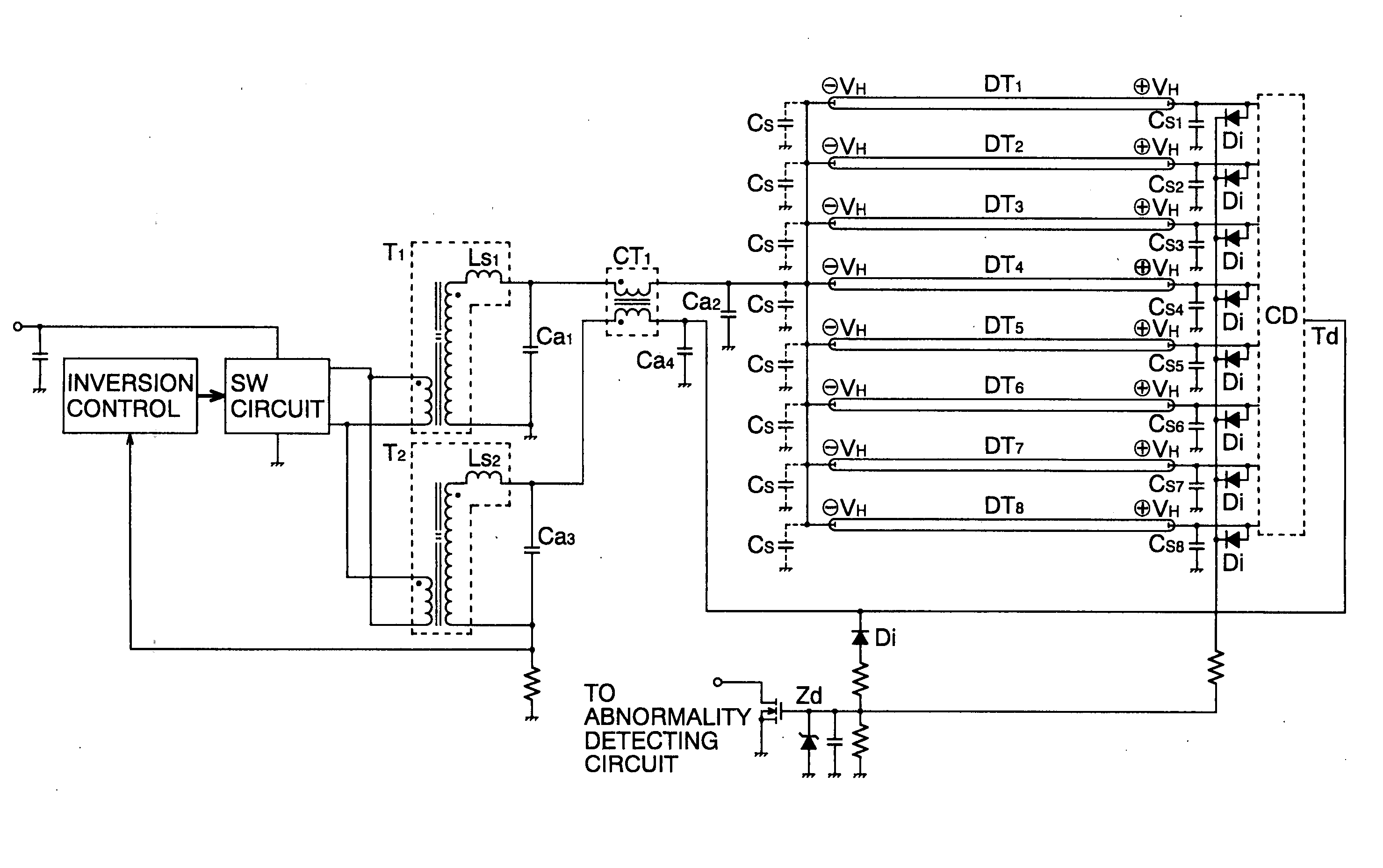
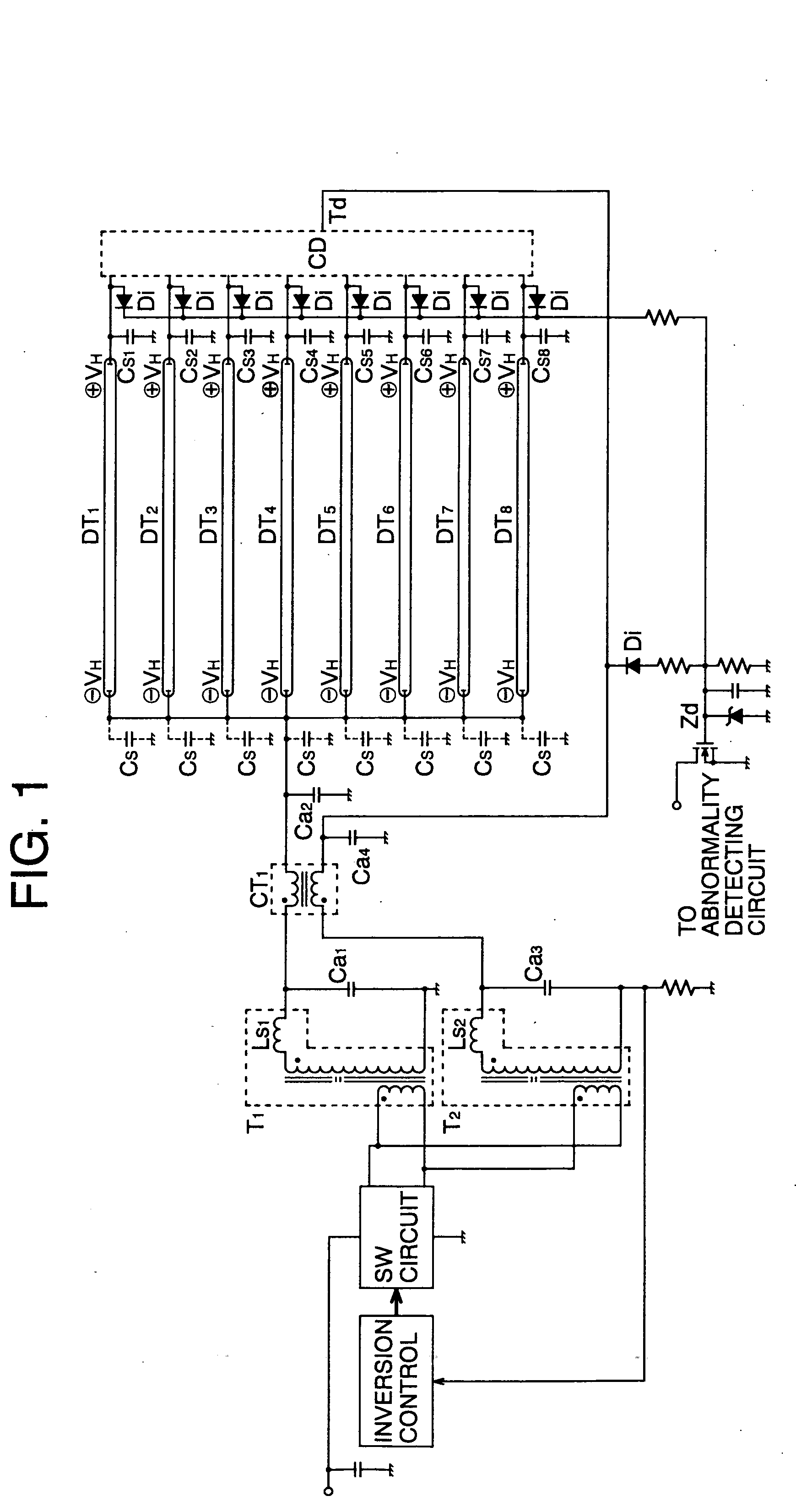
[0077]FIG. 1 is a circuit structural diagram of a double-side high voltage driving system, illustrating one embodiment of the present invention, where an inversion control circuit and a switching (SW) circuit are an oscillation circuit for an inverter circuit and a drive circuit for a step-up transformer. All the inverter circuits that are generally used can be adapted.

[0078] T1 and T2 show leakage flux step-up transformers having leakage inductances (JIS) Ls1 and Ls2 in terms of an equivalent circuit. In circuit diagrams which are to be illustrated simply, the leakage inductance (JIS) Ls may be omitted from the description. Although such a description is not correct one based on the ISO description, it is often customary to make such omission among those skilled in the related art.

[0079] Cw1 and Cw2 are parasitic capacitances between windings, and Ca1, Ca2, Ca3 and Ca4 are auxiliary ...


PUM


Abstract

Disclosed is a low-cost parallel lighting system for discharge lamps for a surface light source, which reduces nonuniform brightness and static noise, and fulfills a requirement that lamp currents of individual cold-cathode fluorescent lamps should be uniform and stabilized. In a surface light source system having multiple discharge lamps, there is a module which lights the discharge lamps in parallel and whose input terminal and electrodes on an opposite side to that side of the discharge lamps which is connected to the module are driven by voltage waveforms different in phase by 180 degrees from each other, wherein an input terminal of an opposite phase of the surface light source system is connected to an inverter circuit having outputs of opposite phases via a single shunt transformer in such a way as to cancel out magnetic fluxes generated by currents respectively flowing in windings of the shunt transformer, whereby the resonance frequency of the inverter circuit having outputs of opposite phases is matched to balance the outputs.

Description

[0001] This application claims priority to Japanese Patent application Nos. 2004-79571 filed on 19 Mar. 2004 and 2004-326485 filed on 10Nov. 2004. TECHNICAL FIELD [0002] The present invention relates to an application of the invention disclosed in U.S. Pat. No. 5,495,405 (corresponding to Japanese Patent No. 2733817) by the inventors of the present invention or the use of the technical subject matters of that invention, and pertains a parallel lighting system for elongated discharge lamps for a surface light source which require a high voltage, such as a cold-cathode fluorescent lamp (CCFL), an external electrode fluorescent lamp (EEFL) and a neon lamp, for use in a large surface light source system for liquid crystal display televisions, general-purpose illumination and the like. BACKGROUND OF THE INVENTION [0003] Recently, backlights for liquid crystal display are becoming larger and cold-cathode fluorescent lamps to be used for backlights are becoming longer. [0004] Accordingly, ...

Claims


Application Information

Patent Timeline
IPC IPC(8): H02M7/48H05B41/24H05B41/282
CPCH05B41/2827H02M7/48H05B41/245G02F1/1336F21K2/08
Inventor USHIJIMA, MASAKAZUTAIDO, DAISUKE
Owner USHIJIMA
Why Eureka
Try Eureka