Magnetic film forming method, magnetic pattern forming method and magnetic recording medium manufacturing method
a technology of magnetic film and manufacturing method, which is applied in the direction of magnetic bodies, instruments, record information storage, etc., can solve the problems of inability to meet the needs of users, so as to achieve the effect of reducing the manufacturing cos
- Summary
- Abstract
- Description
- Claims
- Application Information
AI Technical Summary
Benefits of technology
Problems solved by technology
Method used
Image

Examples
example 1
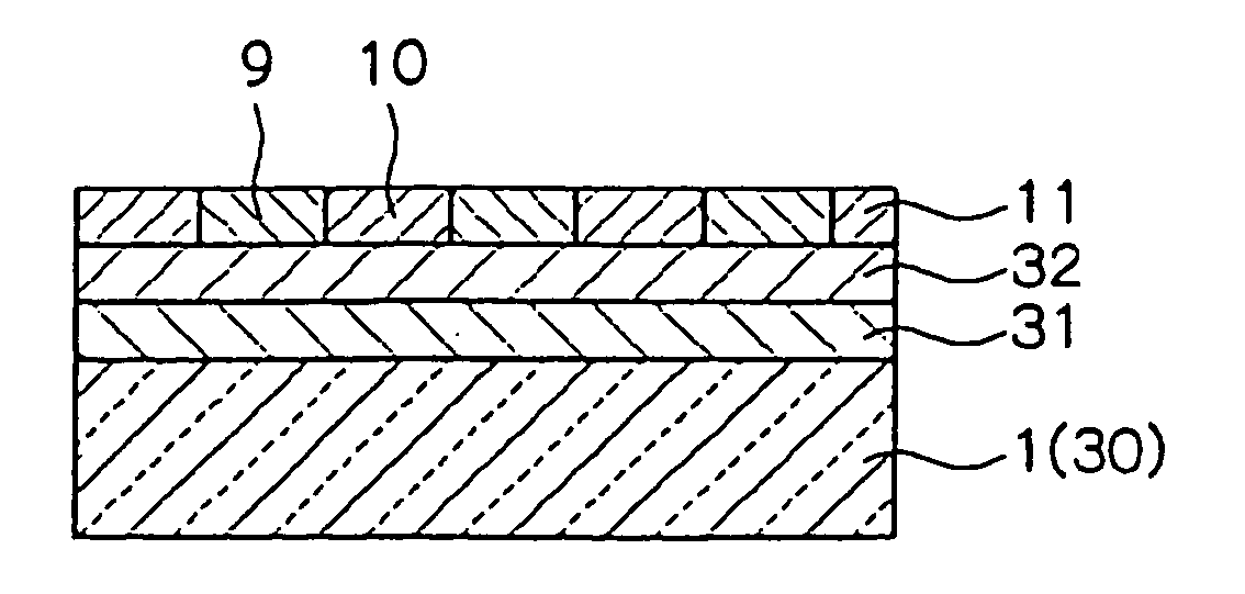
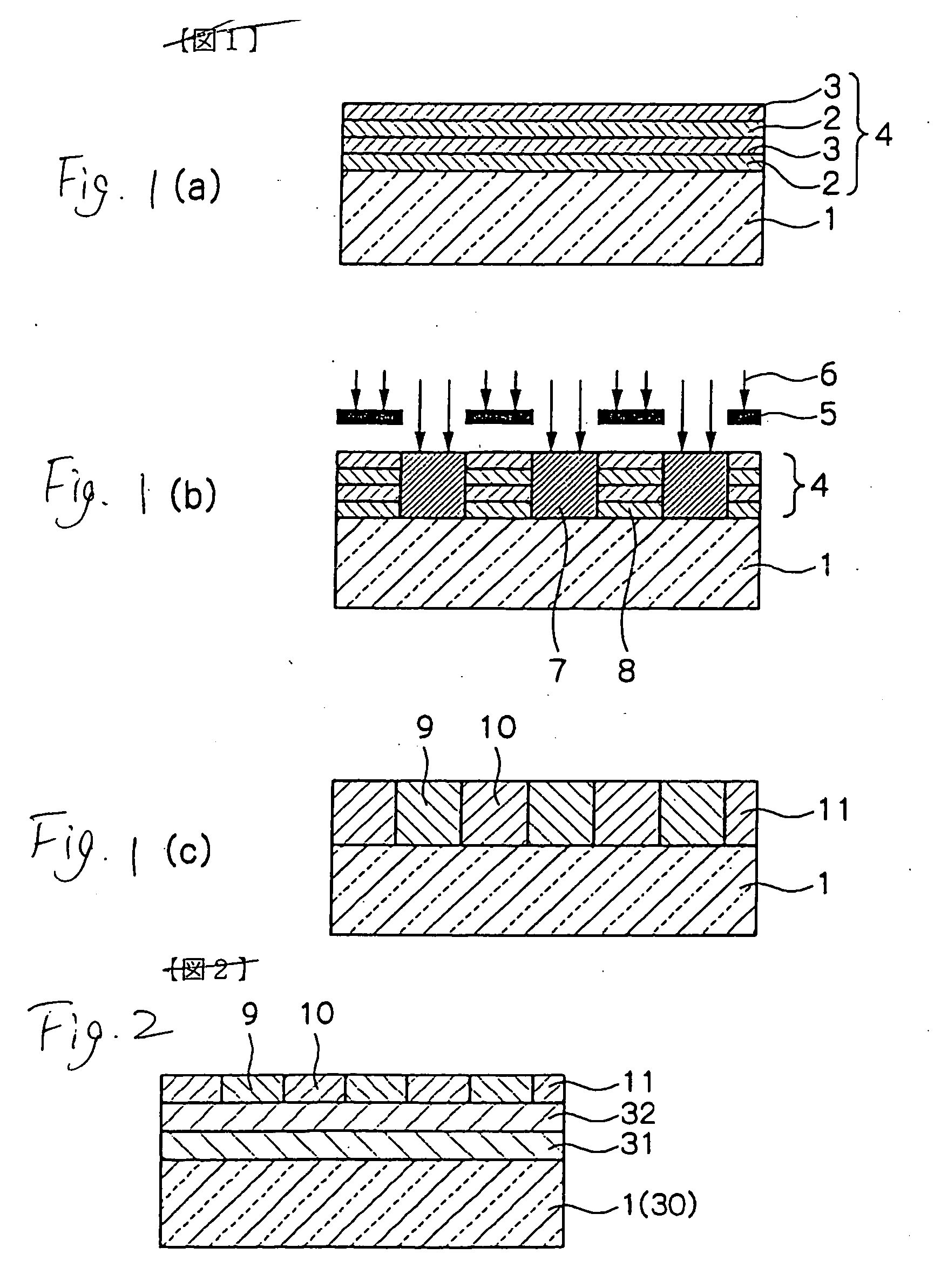
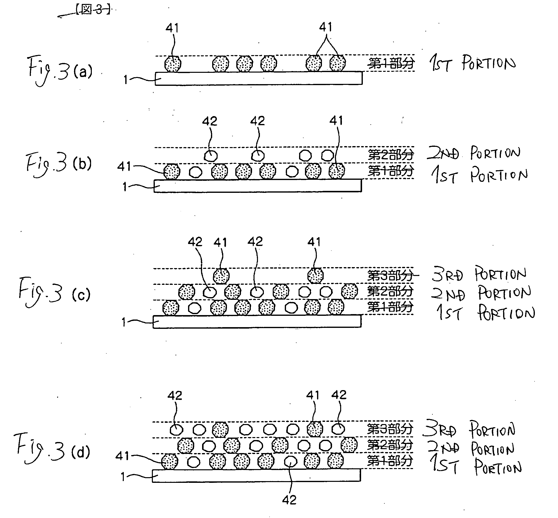
[0066] By using a glass substrate having a thickness of 0.635 mm as the non-magnetic substrate 30, NiFeNb was formed thereon by sputtering so as to be the underlayer film 31 in a thickness of 150 nm, and furthermore, MgO was formed thereon by the sputtering so as to be the intermediate film 32 in a thickness of 3 nm. A Pt atom 41 corresponding to 75% of a necessary amount for forming a Pt single atomic layer was deposited, by the sputtering, on the intermediate film 32 thus formed, and subsequently, an Fe atom 42 corresponding to 75% of a necessary amount for forming an Fe single atomic layer was deposited by the sputtering. Then, the deposition of the Pt atom 41 and that of the Fe atom 42 were alternately repeated, and the depositions were alternately carried out until the number of repetitions is 63. Thus, a thin film was formed. The thin film thus obtained was a compositionally modulated film having a ratio of the Pt atom 41 to the Fe atom 42 of 3:1, 1:1 and 1:3 as one cycle resp...
example 2
[0070] Four types of films (samples 9 to 12) were fabricated in the same manner as in the example 1 except that an implanting voltage was set to be 20 keV to carry out implantation. In the samples 9 to 12, as shown in Table 2, the Ag ion was implanted into the thin film in the amounts of implantation of 1 to 3 atomic % at an implanting voltage of 20 keV Referring to the magnetic characteristic of the film thus fabricated, a coercive force Hc in an in-plane direction and a saturation magnetization Ms were measured by means of a vibration sample type magnetometer (VSM) respectively in the same manner as in the example 1. A result is shown in Table 2.
TABLE 2Amount ofSaturationimplantation of AgCoercive forcemagnetization(atomic %)(Oe)(G)Sample 1062001050Sample 9190131030Sample 10211880880Sample 112.510810820Sample 12310320800
[0071] As is apparent from the result of the Table 2, in case of the samples 9 to 12 according to the invention, all of them had large coercive forces and a diff...
example 3
[0072] Three types of films (samples 13 to 15) were fabricated in the same manner as in the example 1 except that an implanting voltage was set to be 60 keV to carry out implantation. In the samples 13 to 15, as shown in Table 3, the Ag ion was implanted into the thin film in the amounts of implantation of 1 to 2.5 atomic % at an implanting voltage of 60 keV Referring to the magnetic characteristic of the film thus fabricated, a coercive force Hc in an in-plane direction and a saturation magnetization Ms were measured by means of a vibration sample type magnetometer (VSM) respectively in the same manner as in the example 1. A result is shown in Table 3.
TABLE 3Amount ofSaturationimplantation of AgCoercive forcemagnetization(atomic %)(Oe)(G)Sample 1062001050Sample 1319753990Sample 14211150820Sample 152.512850760
[0073] As is apparent from the result of the Table 3, in case of the samples 13 to 15 according to the invention, all of them had large coercive forces and a difference from ...
PUM
| Property | Measurement | Unit |
|---|---|---|
| Percent by atom | aaaaa | aaaaa |
| Percent by atom | aaaaa | aaaaa |
| Percent by atom | aaaaa | aaaaa |
Abstract
Description
Claims
Application Information
 - R&D
- Intellectual Property
- Life Sciences
- Materials
- Tech Scout
- Unparalleled Data Quality
- Higher Quality Content
- 60% Fewer Hallucinations
Browse by: Latest US Patents, China's latest patents, Technical Efficacy Thesaurus, Application Domain, Technology Topic, Popular Technical Reports.
© 2025 PatSnap. All rights reserved.Legal|Privacy policy|Modern Slavery Act Transparency Statement|Sitemap|About US| Contact US: help@patsnap.com