Electrode formation method, electrode and solar battery

a solar battery and electrode technology, applied in the direction of basic electric elements, electrical equipment, semiconductor devices, etc., can solve the problems of screen mesh clogging up, inability to obtain inability to achieve a predetermined line width, etc., to achieve high aspect ratio

Inactive Publication Date: 2005-10-06
SHARP KK
View PDF2 Cites 72 Cited by
  • Summary
  • Abstract
  • Description
  • Claims
  • Application Information

AI Technical Summary

Benefits of technology

[0013] It is an object of the present invention to provide a method for forming an electrode capable of solving the conventional disadvantages, dispensing with a screen mask, and ensuring a high aspect ratio, and an electrode formed by using this method, and a solar battery including this electrode.

Problems solved by technology

If the line width of the sub-electrode is narrowed, a screen mesh clogs up and breaking of the line or inability to obtain a predetermined line width occurs.
Due to this, it is difficult to narrow the line width of the sub-electrode.
In addition, a screen mask is easily broken even by a low impact and care should be therefore taken of to handle the screen mask.
If the diameter of the nozzle is reduced so as to narrow the line width of the electrode, the paste clogs up, resulting in breaking of the electrode.

Method used


Image

  • Electrode formation method, electrode and solar battery
  • Electrode formation method, electrode and solar battery
  • Electrode formation method, electrode and solar battery

Examples


example 1

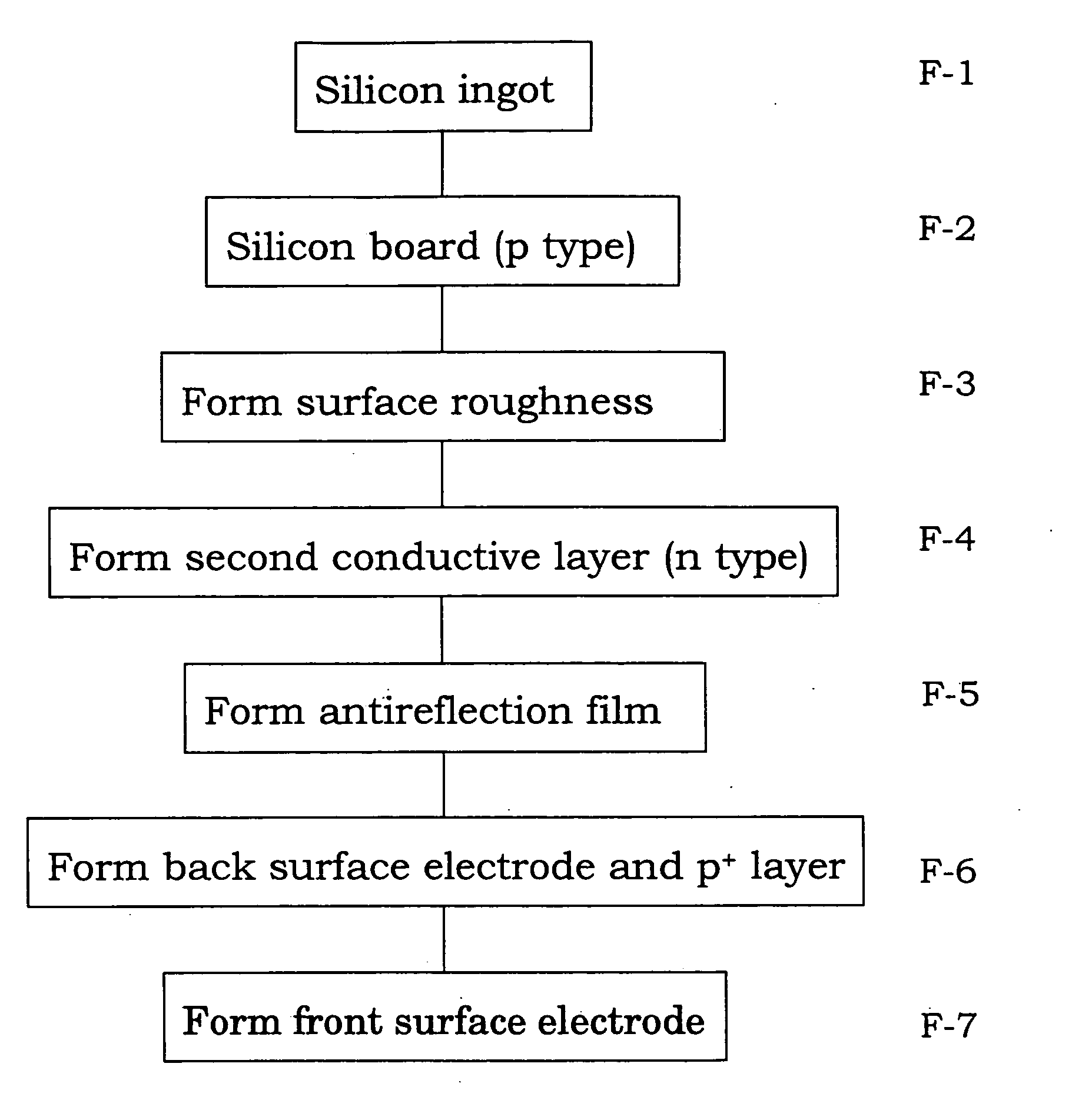
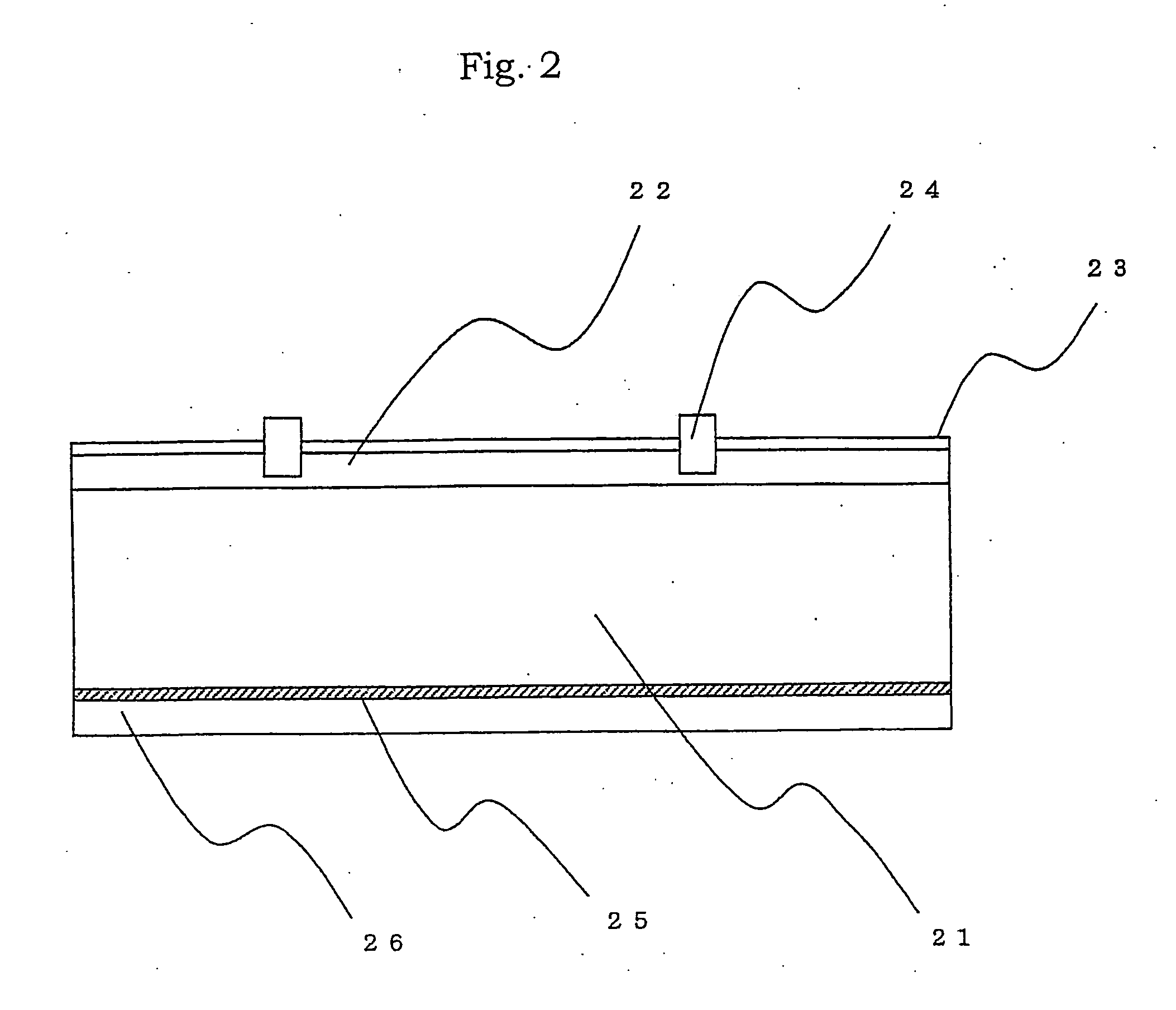
[0052] The solar battery cell shown in Example 1 generally has the cross-sectional structure shown in FIG. 2. The manufacturing of this cell was based on the flowchart shown in FIG. 3.

[0053] First, the p type polycrystalline silicon substrate 21 obtained by slicing the silicon ingot and having an outer size of 10×10 cm, a thickness of 0.35 mm and a specific resistance of about 2 Ωcm was prepared. The surface of the silicon substrate 21 was etched by a depth of 20 μm at 80° C. for 10 minutes in a solution obtained by adding 7% alcohol to a 5% NaOH alkaline aqueous solution. Surface roughness was formed simultaneously with removal of a pulverized layer. Although a height of the surface roughness was around 5 μm to 10 μm microscopically, the silicon substrate 21 was flat as a whole.

[0054] Next, the etched silicon substrate 21 was mounted on a jig in an electric furnace at 840° C. in a POCl3 containing atmosphere, and phosphorus ions were diffused onto the silicon substrate 21 for 20 ...

example 2

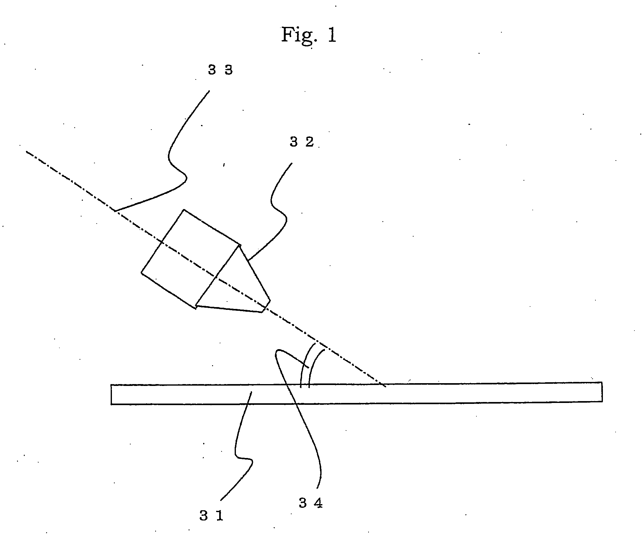
[0063] In Example 2, manufacturing conditions were the same as those according to Example 1 except that the thickness of the p type polycrystalline silicon substrate 21 was 0.15 mm and the nozzle angle was 20°. As a result, a line width and an aspect ratio were about 110 μm and 0.35 similar to those according to Example 1 (see Table 2).


PUM


Abstract

A method for forming an electrode according to the present invention includes a step of discharging a paste containing an electrode material from a discharge port of a nozzle, and drawing a fine-line pattern on a surface of a semiconductor substrate, and a step of drying and baking the drawn fine-line pattern, and forming a fine-line electrode. Herein, in the drawing step, the nozzle is arranged so that a central axis of the nozzle is inclined at a predetermined inclination angle with respect to the surface of the semiconductor substrate, and so that the discharge port is proximate to the surface of the semiconductor substrate at a predetermined distance, the nozzle and the semiconductor substrate are moved relatively to each other in a drawing direction of the fine-line pattern, and relative movement speeds of the nozzle and the semiconductor substrate are adjusted, thereby drawing the fine-line pattern so that a line width of the fine-line pattern is smaller than an inner diameter of the discharge port of the nozzle.

Description

CROSS-REFERENCE TO RELATED APPLICATION [0001] This application is related to Japanese application No.2004-167293 filed on Jun. 4, 2004 whose priority is claimed under 35 USC §119, the disclosure of which is incorporated by reference in its entirety. BACKGROUND OF THE INVENTION [0002] 1. Field of the Invention [0003] The present invention relates to an electrode formation method, an electrode and a solar battery. More specifically, the present invention relates to a method for forming an electrode used in a solar battery or the like, an electrode formed by using this method, and a solar battery including this electrode. [0004] 2. Description of the Related Art [0005] Examples of a method for forming an electrode as one of solar battery manufacturing steps include a deposition method, a plating method, a printing method, a drawing method and the like. At present, with a view of cost reduction and mass production in the solar battery, screen printing is widely used. [0006] With this sc...

Claims


Application Information

Patent Timeline
Patent Type & Authority Applications(United States)
IPC IPC(8): H01L21/44H01L31/0224H01L31/04H01L31/068H01L31/18
CPCH01L31/022425H01L31/068Y02E10/547
Inventor OZAKI, RYOHOHTA, HITOMIFUKUMURA, HIROYUKITAKABA, YOSHIROHKOMATSU, YUJINUNOI, TOHRU
Owner SHARP KK
Why Eureka
Try Eureka