Method and apparatus for controlling and protecting pulsed high power fiber amplifier systems

Inactive Publication Date: 2005-10-13
IMRA AMERICA
View PDF19 Cites 119 Cited by
  • Summary
  • Abstract
  • Description
  • Claims
  • Application Information

AI Technical Summary

Benefits of technology

[0015] Means are also provided to monitor the repetition rate of the injected pulses into the amplifier system, to compare it to a predetermined minimum repetition rate, and if lower than this minimum repetition rate, to disable or reduce the current to the amplifier pump diode to prevent it from being damaged.
[0016] The exemplary device discussed above also provides a means for comparing the amplitude of the pulse

Problems solved by technology

However, the build-up time of amplified noise in such a system is the round-trip time of the total fiber amplifier length which is 10-100 ns and not the fluorescence lifetime which is 400 μs

Method used


Image

  • Method and apparatus for controlling and protecting pulsed high power fiber amplifier systems
  • Method and apparatus for controlling and protecting pulsed high power fiber amplifier systems
  • Method and apparatus for controlling and protecting pulsed high power fiber amplifier systems

Examples


Embodiment Construction

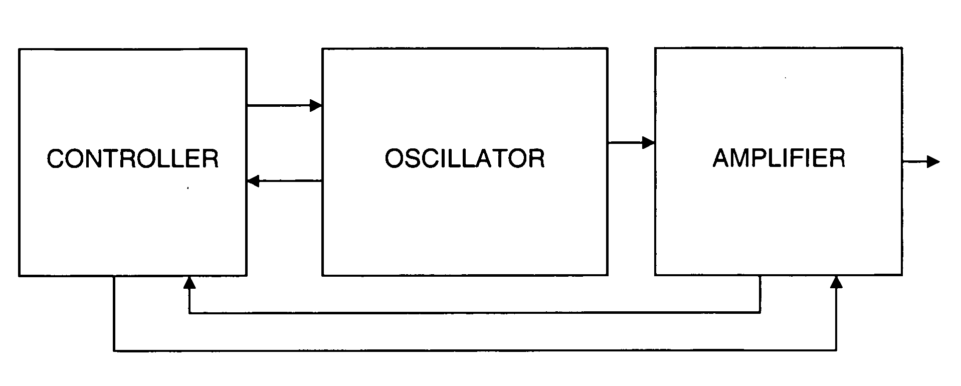
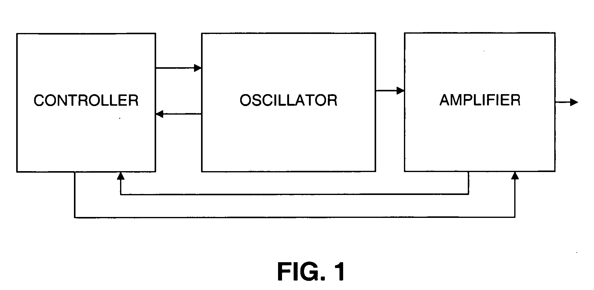
[0030] A general block diagram of the present invention is shown in FIG. 1. As shown, a system in accordance with the invention includes an oscillator, an amplifier and a controller. The controller has the ability to control and monitor various parameters of both the oscillator and amplifier. FIG. 8 illustrates an exemplary oscillator and its monitoring and control functions. The electric current, optical power and temperature of the oscillator pump diode can be monitored and controlled. This is accomplished by using a temperature sensor such as a thermistor to monitor the diode temperature and using a cooling device such as a thermoelectric cooler to adjust the diode temperature. The optical power of the laser diode is typically monitored using a back facet photodiode.

[0031] The temperature, current, wavelength, and repetition rate of the oscillator can be monitored and controlled. These properties are controlled to give better stability to the system. The wavelength variation of ...


PUM


Abstract

An electronic circuit for controlling a laser system consisting of a pulse source and high power fiber amplifier is disclosed. The circuit is used to control the gain of the high power fiber amplifier system so that the amplified output pulses have predetermined pulse energy as the pulse width and repetition rate of the oscillator are varied. This includes keeping the pulse energy constant when the pulse train is turned on. The circuitry is also used to control the temperature of the high power fiber amplifier pump diode such that the wavelength of the pump diode is held at the optimum absorption wavelength of the fiber amplifier as the diode current is varied. The circuitry also provides a means of protecting the high power fiber amplifier from damage due to a loss of signal from the pulse source or from a pulse-source signal of insufficient injection energy.

Description

FIELD OF THE INVENTION [0001] This invention relates generally to a pulsed laser system comprising a high power fiber amplifier and a pulsed seed source. One embodiment in accordance with the invention uses an electronically controlled semiconductor diode laser as the seed source. The seed source may also be a mode-locked laser. BACKGROUND OF THE INVENTION [0002] Pulse laser systems consisting of an oscillator and a high power fiber amplifier have been developed and are well known in the art. See, for example, U.S. Pat. Nos. 6,208,458; 6,181,463; and 5,696,782, all of which are assigned to the same assignee as the present invention and all of which are included herein by reference for all that they teach. Conventional systems of this type typically operate at a fixed pulse width and repetition rate. However, systems with variable pulse widths and repetition rates have also been developed. For example, see U.S. Pat. Nos. 6,347,007; 6,335,941; and 6,433,306 to Grubb et al. For certain...

Claims


Application Information

Patent Timeline
IPC IPC(8): H01S3/067H01S3/0941H01S3/098H01S3/10H01S3/105H01S3/13H01S3/131H01S3/23H04B10/12
CPCH01S3/06758H01S3/0941H01S3/10015H01S3/1003H01S3/10038H01S3/1112H01S3/105H01S3/1305H01S3/1312H01S3/1394H01S3/06779H01S3/10046
Inventor NATI, SALVATORE F.ULRICH, OTHO E. JR.CHO, GYU CHOENGILLIS, WAYNE A.HARTER, DONALD J.BENDETT, MARKHARTL, INGMAR
Owner IMRA AMERICA
Why Eureka
Try Eureka