[0005] In the showerhead system, a precursor can be fed onto a substrate at a uniform concentration distribution or at a prescribed concentration distribution. To achieve a uniform concentration distribution, controlling of conductance from the showerhead to the substrate by a distribution plate is necessary, which triggers hindering of reaction gas purging from the showerhead. Because at least two different reaction gases are fed alternately, after Reaction Gas A is fed, Reaction Gas B often can be fed only after purging Reaction Gas A is completed. Thus, an approach to feed Reaction Gas A and Reaction Gas B uniformly from the showerhead via different gas paths, hence, is effective, wherein Reaction Gas A and Reaction Gas B are made to react only on a substrate surface.
[0006] Additionally, as another approach to quickly purge Reaction Gases A and B from the showerhead respectively, an exhaust port is provided on at least one side to evacuate the inside of the showerhead in a short period of time during gas purging. This method is able to solve a problem, which conventionally hinders
atomic layer deposition by the showerhead.
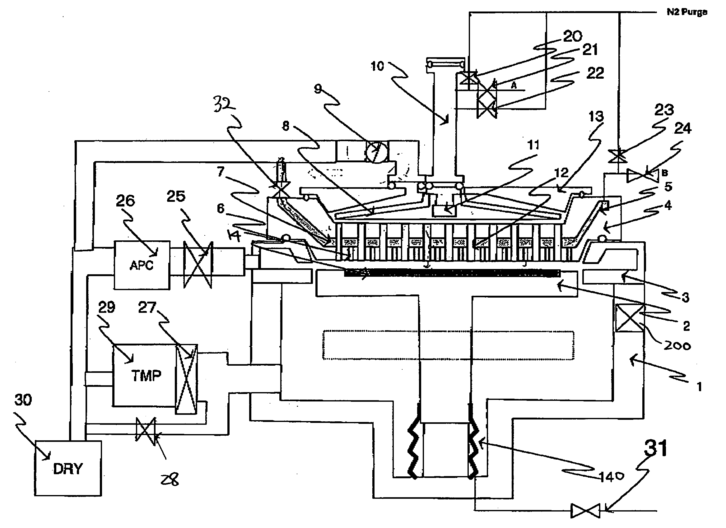
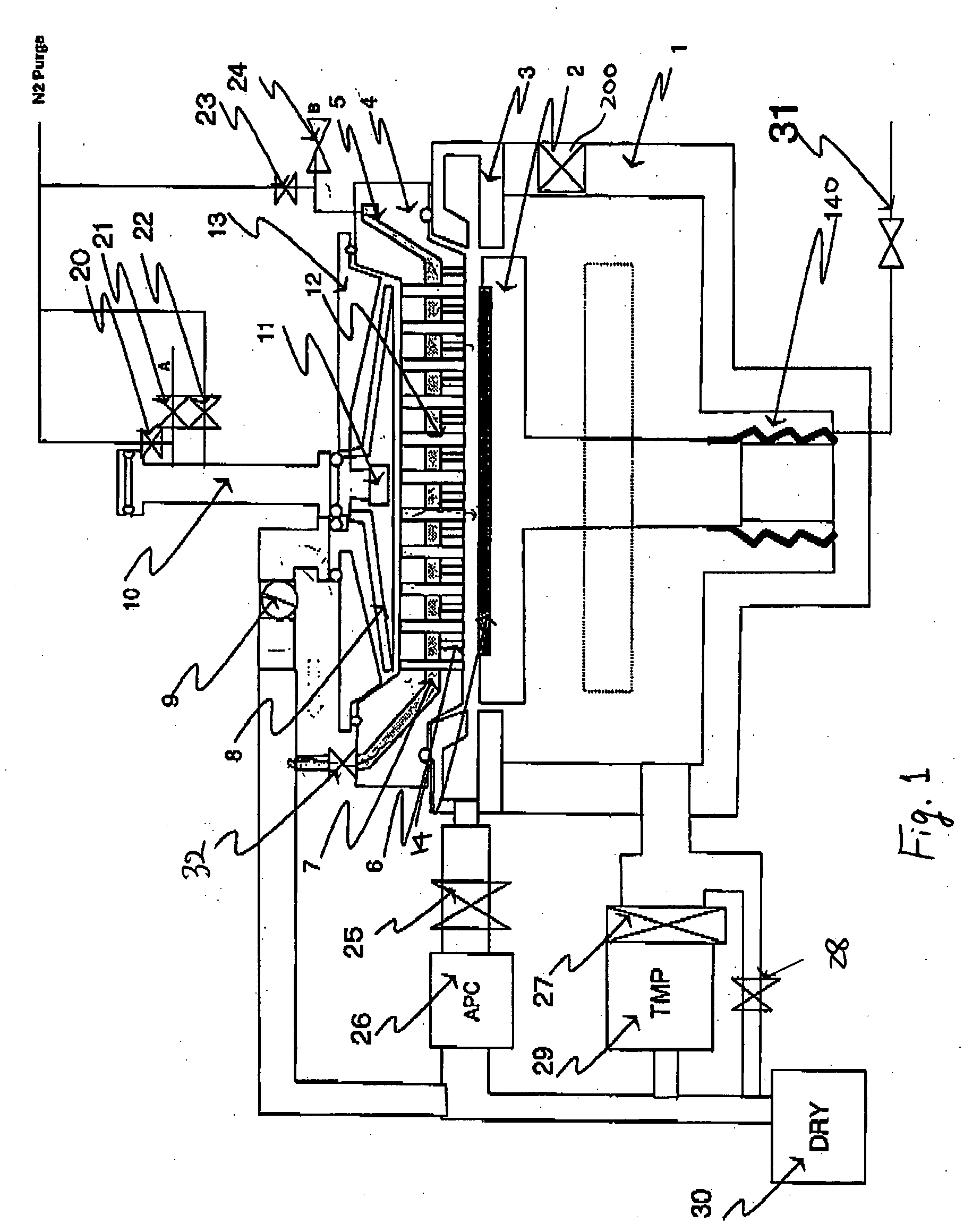
[0008] In view of the foregoing, in an embodiment, the present invention provides a gas-feeding apparatus configured to be connected to an evacuatable
reaction chamber provided with a support for placing a substrate thereon, comprising: a gas-distribution head for introducing gases into the chamber through a head surface, which gas-distribution head comprises a first section for discharging a gas through the head surface toward the support and a second section for discharging a gas through the head surface toward the support, said first and said second sections being isolated from each other in the gas-distribution head, at least one of which section is coupled to an exhaust system for exhausting a gas present in the corresponding section without passing through the head surface. In the above embodiment, the gas-feeding apparatus comprises multiple gas lines or systems, at least one of which is coupled to an exhaust system, so that multiple gases can be used very efficiently due to rapid or instant purging operation. The gas present in the section can be purged without passing through the head surface, e.g., a showerhead lower surface having a plurality of bores. A low-
vapor pressure primary material and a low molecular weight secondary material can be effectively used.
[0012] In yet another embodiment, the present invention is characterized in that a showerhead used for, e.g., atomic layer growth
processing by feeding two or more different gases alternately has two or more separate gas-distribution paths, and that a means for exhausting the inside of the showerhead, which is communicated with at least one gas-distribution path. Additionally, in this embodiment, a
plasma can be generated either between the showerhead and a substrate surface, or inside the showerhead. Additionally, in an embodiment, when a
plasma is generated, the present invention may be characterized in that a gas-distribution portion not communicated with an exhaust path is at least provided on the substrate side, rather a gas-distribution portion communicated with the exhaust path is provided. Even if the gas-distribution portion not communicated with an exhaust path is provided on the substrate side, it is possible to make it communicated with an exhaust path disposed downstream of the showerhead. Providing an exhaust path on a side which is more remote from a substrate than the other side, however, makes the path more efficient, hence advantageous. This may be because it is difficult to feed a low-vapor-pressure material gas under
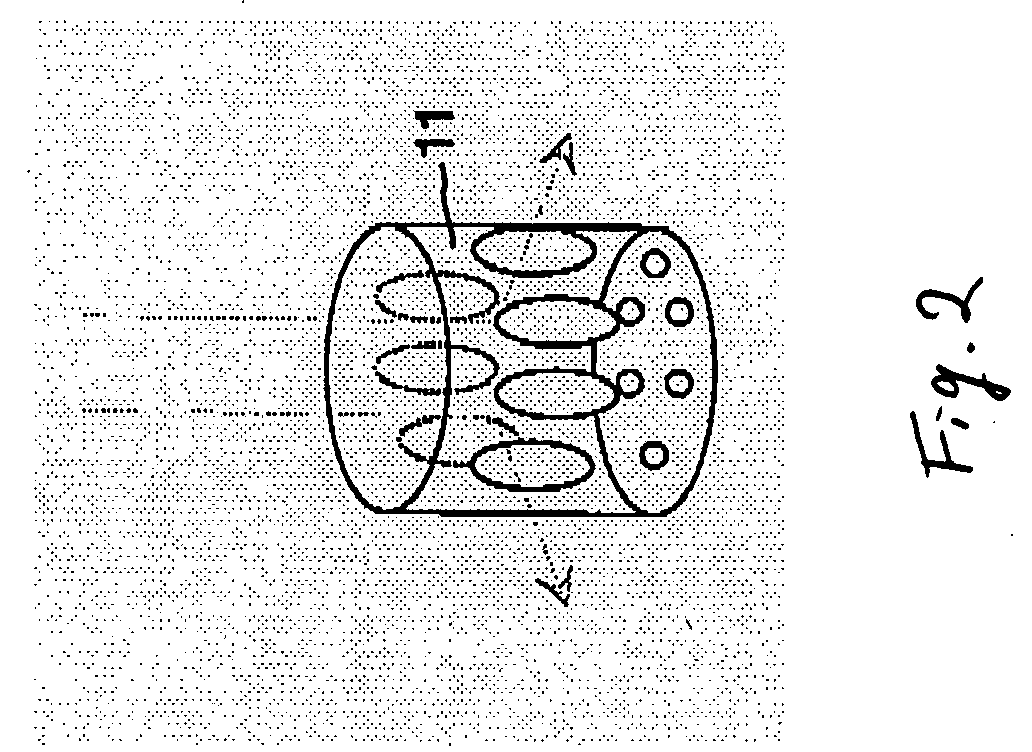
high pressure, and to introduce a low-vapor-pressure material gas into the showerhead under relatively low pressure, a sufficient capacity or space for diffusing the gas may be required. For this purpose, in an embodiment, providing a distribution chamber with a larger capacity on the side away from the substrate is advantageous. Additionally, because this structure allows the gas to be introduced to the center of the chamber, the gas can be distributed more uniformly.
[0013] As described above, using a post-mixing type showerhead, a thin-film deposition apparatus according to an embodiment of the present invention is able to feed material gases extremely uniformly while vapor-
phase reaction of material gases having high reactivity is controlled by setting up a dedicated exhaust port with a valve which opens / closes rapidly, or a variable conductance valve in respective gas-distribution chambers, wherein purging the remaining gas can be completed at high speeds, e.g., in about 10 msec to about 500 msec (including 25 msec, 50 msec, 100 msec, 200 msec, 300 msec, and ranges of any two of the foregoing, preferably about 50 msec to about 100 msec), depending on the conductance of the exhaust system. Conventionally, evacuating the reaction gas remaining inside the showerhead in a short period of time was not feasible. Consequently, in an embodiment of the present invention, it becomes possible to form a uniform thin film with
high productivity rates, which never could be achieved before, and with no or fewer particles. Additionally, in the case of a reaction, which becomes chemically active only when RF is applied to one of gases, stopping plasma application stops the reaction, hence no purging is required for the one of gases. In this case, by setting up a dedicated exhaust port and an
exhaust valve only in a distribution chamber to which a
metal material gas is introduced, a thin film can be formed extremely efficiently.

