Method and apparatus for calibrating a frequency domain reflectometer

a frequency domain and reflectometer technology, applied in the field of down conversionless systems, can solve the problems of material properties changing, faults at the interface between two cables, rf transmission lines and waveguides can become faulty, etc., and achieve the effect of accurate estimation of the complex reflection coefficient frequency profile and reduced computational complexity

Inactive Publication Date: 2005-10-20
BAE SYST INFORMATION & ELECTRONICS SYST INTERGRATION INC
View PDF6 Cites 45 Cited by
  • Summary
  • Abstract
  • Description
  • Claims
  • Application Information

AI Technical Summary

Benefits of technology

[0035] As a result of the above techniques, an accurate estimate of the complex reflection coefficient frequency profile can be measured. Also, because the Inverse Fourier Transform operates on a complex value of the reflection coefficient after calibration, ghosts due to the multiple faults, non-linearities are eliminated. This is unlike prior Inverse Fourier Transform systems, which operate on the absolute magnitude of the reflection coefficient that does not take into account that the reflection coefficient is complex. Since it is, one can take advantage of this fact to correctly model the transmission line and therefore eliminate one source of ghosts.
[0036] Secondly, because the modified Inverse Fourier Transform takes into account line atten...

Problems solved by technology

Likewise, for satellite and terrestrial-based communications, RF transmissions lines and waveguides can become faulty, especially at the interface between two cables as at a connection, and the ability to identify and locate the fault is a paramount concern.
A fault is anything that causes a change of impedance in the material properties of the cable or waveguide that causes some of the energy that is being transmitted through the transmission line to be reflected.
Typically the faults occur at the interface between two cables, for instance, if a connection is not torqued properly or the connectors are old.
Thus, cable discontinuities or faults can be the result of interface problems between the cables or when a cable is bent and tweaked enough, the material properties will change at the bend that cause a reflection.
Also, if the shielding to the cable is damaged in any way, part of the cable may couple to, for instance, the body of an aircraft, causing an impedance mismatch.
However, when one starts to get into high frequency applications exceeding for example 1 GHz, obtaining a physical system to produce an impulse that is of short enough duration is very difficult to realize in hardware.
Moreover, even if one can create such a short pulse, the shape of the pulse is hard to control.
It is noted that those employing time domain reflectometry do not obtain information on spectral characteristics.
The problem with the methods described in these two patents is that they only measure the amplitude of the reflection coefficient, not the phase.
However, the number of spurious responses increases exponentially with multiple faults.
In short, there are an extremely large number of spurious responses when a device under test contains several faults and removing them all becomes both cumbersome and, in some cases, impossible, at least by visual inspection of the results of an Inverse Fourier Transform (IFT).
Down-conversion adds its own set of problems and involves many local oscillators and mixers.
The result is that one may fail to recognize a subsequent s...

Method used


Image

  • Method and apparatus for calibrating a frequency domain reflectometer
  • Method and apparatus for calibrating a frequency domain reflectometer
  • Method and apparatus for calibrating a frequency domain reflectometer

Examples


Embodiment Construction

[0063] Prior to describing the subject system in detail, a theoretical discussion of the subject system is presented.

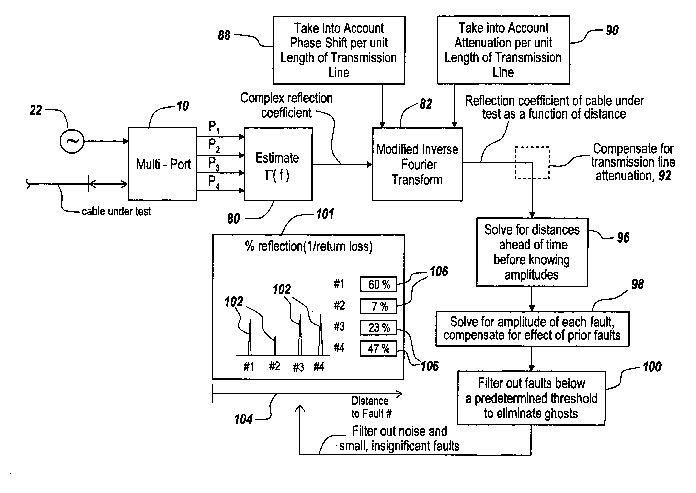
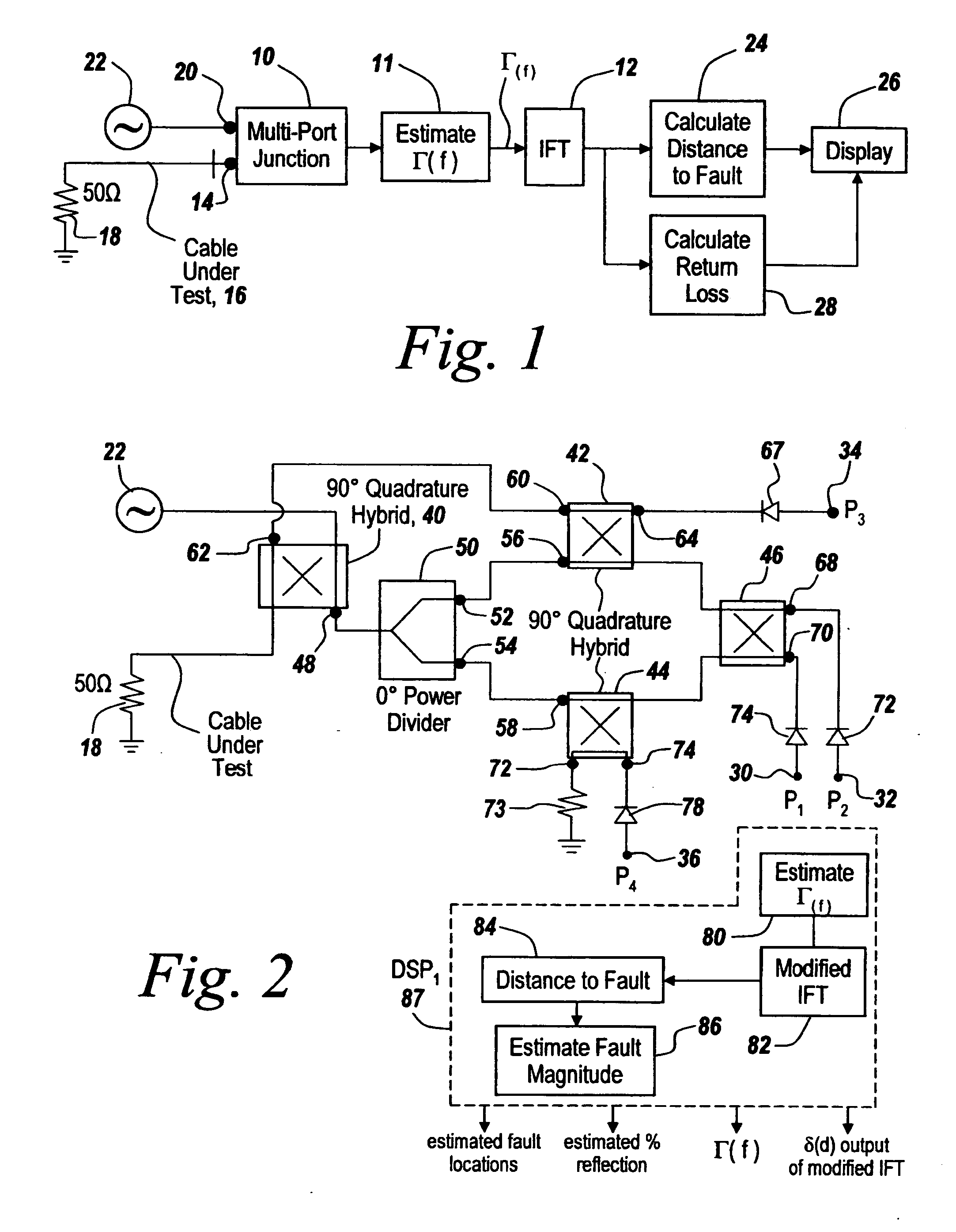
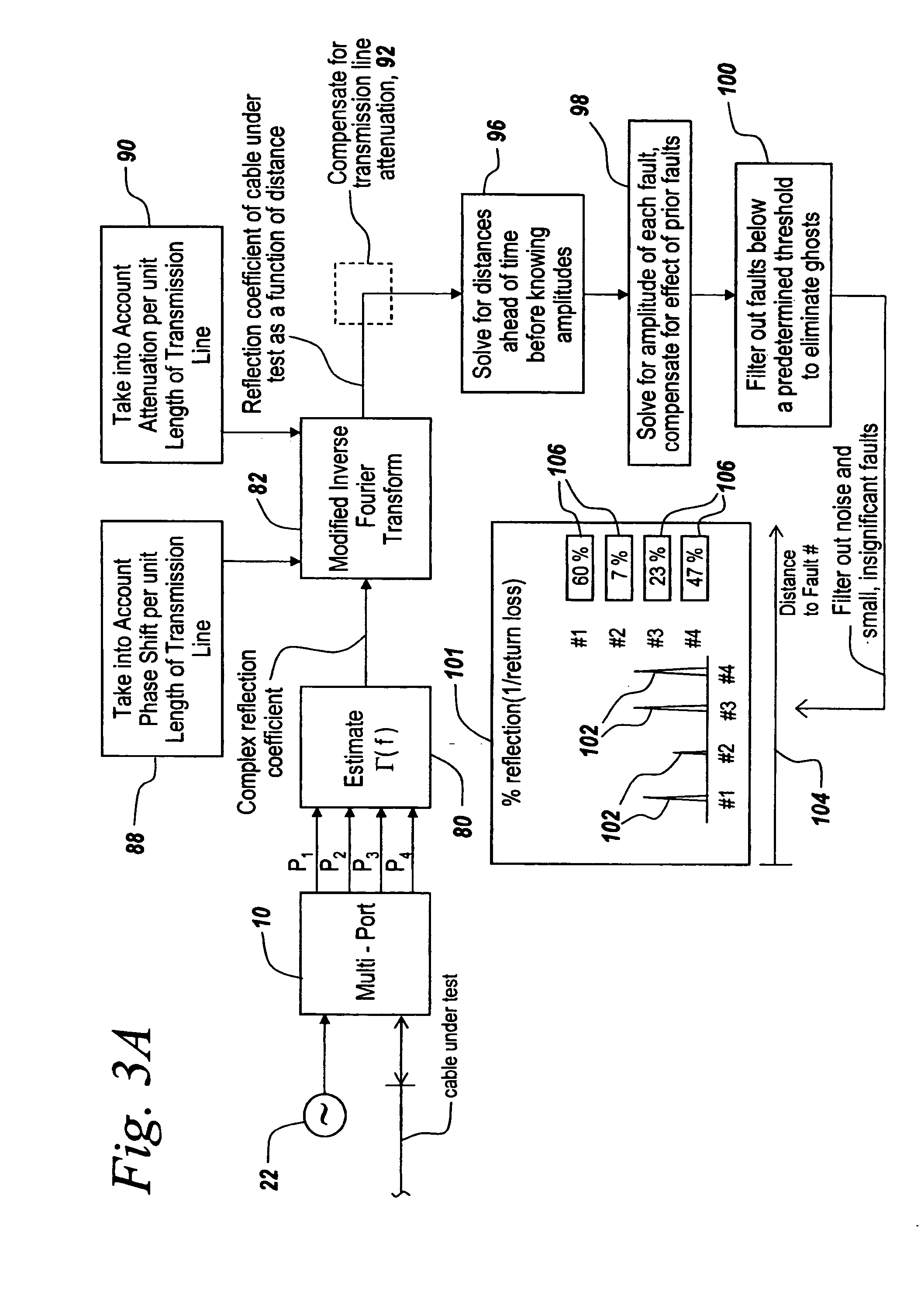
[0064] It is a feature of the subject invention that since the output measurements from the six-port junction involves scaled versions of an RF source plus the returned signal from the cable under test, one can use these measurements to generate a complex reflection coefficient Γ(f) of the entire transmission line, be it a cable or waveguide. This complex reflection coefficient is then used to derive the scattering parameters of the individual faults themselves. Once one has derived the scattering parameters, the distance and severity of a fault can be ascertained.

[0065] As the frequency is stepped or swept, the complex reflection coefficient of the cable is modified by the fault. If it is a perfect cable, then the cable has an impedance that is matched to the measuring circuit. Therefore, all of the energy propagates through the cable to ground and nothing gets ref...


PUM


Abstract

A calibration system is provided for calibrating frequency domain reflectometers in the field by using both the scattering parameters of the multi-port junction determined at the factory and changing the offset and gain terms used in generating a complex reflection coefficient by using internal calibrated loads so that heavy, cumbersome external calibrated transmission lines are not required. In one embodiment the internal calibrated loads include RLC circuits and in another embodiment the internal calibrated loads include attenuators. Further, retesting or recalibration does not necessitate reconnecting the cable under test, which may remain connected to the reflectometer's test port throughout the procedure.

Description

RELATED APPLICATIONS [0001] This application is a Continuation-In-Part of U.S. application Ser. No. 11 / 034,676, filed Jan. 13, 2005 which claims benefit of U.S. Provisional Application No. 60 / 536,886 filed Jan. 15, 2004, and U.S. Patent Application Ser. No. 60 / 536,977 filed Jan. 15, 2004, the contents of which are incorporated herein by reference.FIELD OF THE INVENTION [0002] This invention relates to frequency domain reflectometers and more particularly to a down-conversionless system employing the use of a multi-port junction in combination with an Inverse Fourier Transform. BACKGROUND OF THE INVENTION [0003] It will be appreciated that faults in RF transmission lines and waveguides require detection so that the distance to the fault may be calculated. Moreover, the ability to detect and locate multiple faults that oftentimes result in ghosts that resemble faults requires sophisticated techniques to eliminate the need for skilled technicians. [0004] Nowhere are reflectometers more...

Claims


Application Information

Patent Timeline
IPC IPC(8): G01R27/04G01R35/00G06F19/00H04B3/46
CPCG01R27/04H04B3/46G01R35/005
Inventor NIEDZWIECKI, JOSHUA D.TAYLOR, MATTHEW A.LANDE, MARK
Owner BAE SYST INFORMATION & ELECTRONICS SYST INTERGRATION INC
Why Eureka
Try Eureka