Block-oriented control system on high speed ethernet

Inactive Publication Date: 2005-10-27
GLANZER DAVID A +8
View PDF39 Cites 34 Cited by
  • Summary
  • Abstract
  • Description
  • Claims
  • Application Information

AI Technical Summary

Benefits of technology

[0018] The present invention overcomes the shortcomings described above and provides a new and improved distributed control system, which operates on a high performance backbone, e.g., the standard COTS Ethernet and Internet technology. The embodiments of the present invention are collectively referred to herein as the “High Speed Ethernet” (HSE). HSE includes the features of the distributed control system described by the '178 applicatio

Problems solved by technology

Although Ethernet/Internet technology provides the basic services for a high performance fieldbus backbone, it does not provide for all of the functions needed for use in distributed control systems.
In particular, IEEE and IETF do not have suitable open and interoperable solutions for integration of distributed control systems (e.g., the H1 subsystem), system time synchronization, and fault tolerance.
The method of transferring information from lower speed fieldbuses to the Ethernet used by organizations such as Open DeviceNet™ Vendor Association, Inc., (“EtherNet/IP,”) and PROFIBUS International, (“PROFINet”) are not suitable for use in the high performance environment because they encapsulate the lower speed protocol packets in an Ethernet frame.
This method, known as “tunneling,” i

Method used


Image

  • Block-oriented control system on high speed ethernet
  • Block-oriented control system on high speed ethernet
  • Block-oriented control system on high speed ethernet

Examples


Embodiment Construction

[0032] For simplicity and illustrative purposes, the principles of the present invention are described by referring mainly to exemplary embodiments, particularly, with specific exemplary implementations of distributed control system in an Ethernet network. However, one of ordinary skill in the art would readily recognize that the same principles are equally applicable to, and can be implemented in, other implementations and designs using any other high speed networks, and that any such variation would be within such modifications that do not depart from the true spirit and scope of the present invention.

A: HSE Distributed Control System Overview

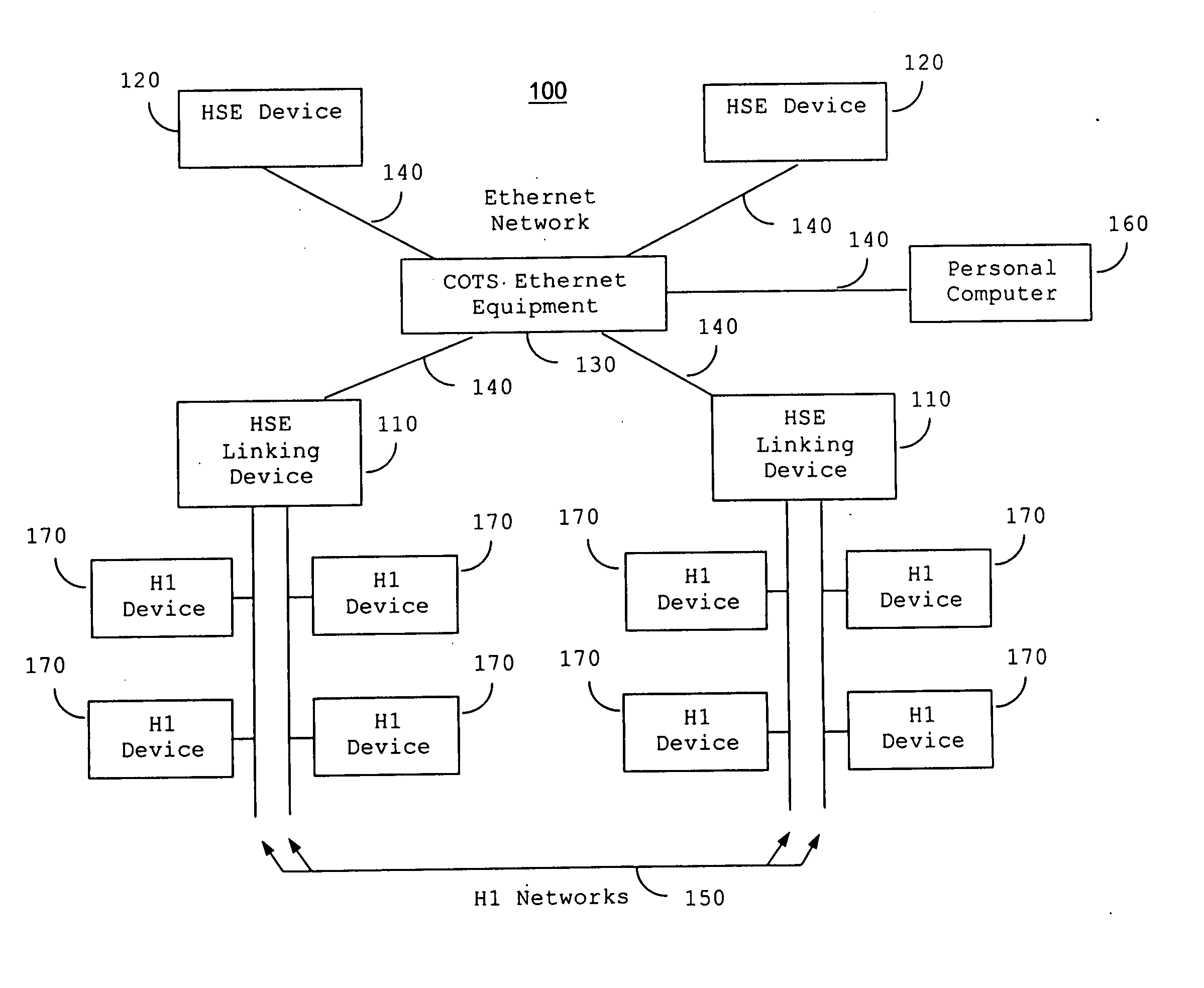
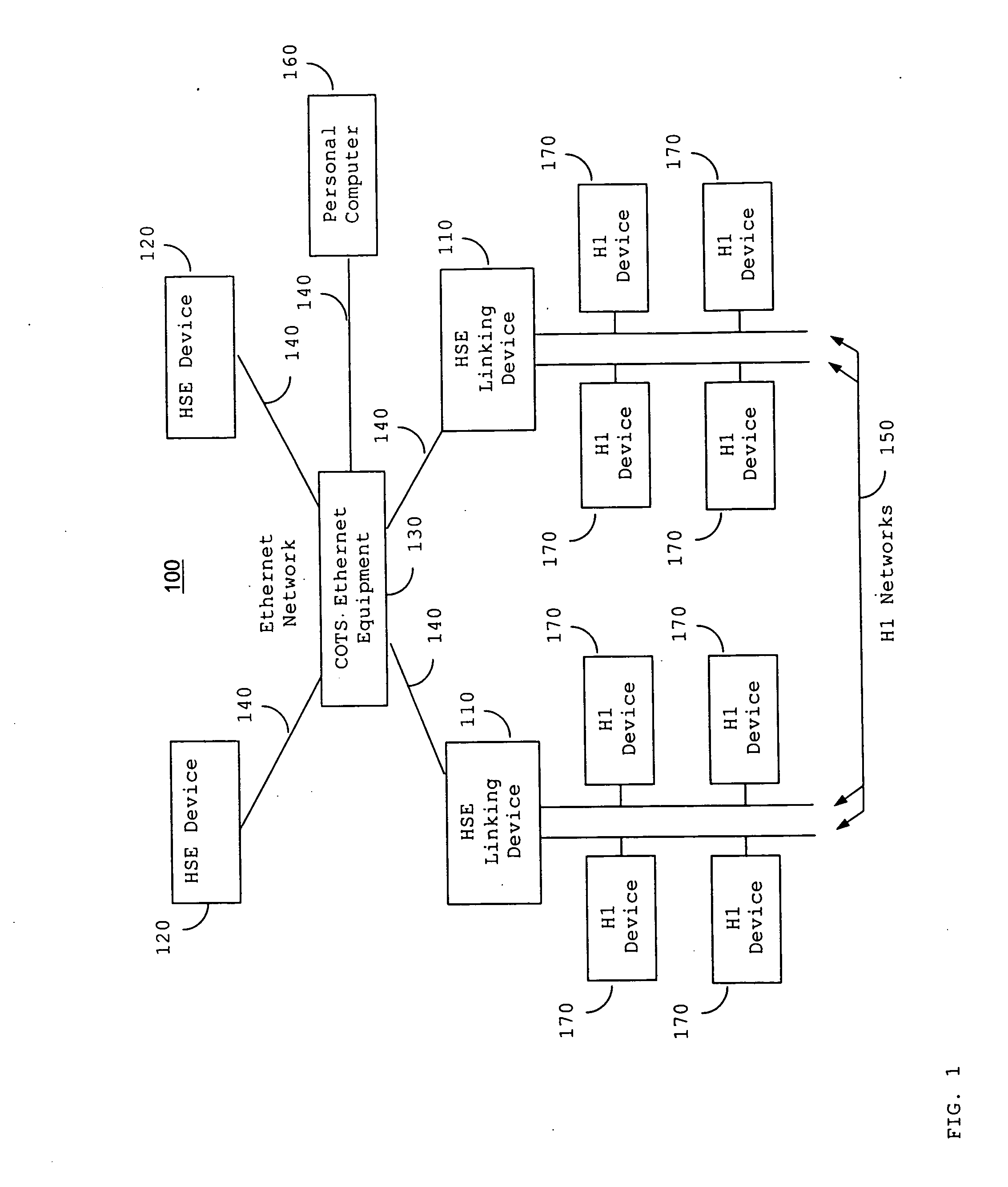
[0033] Referring to FIG. 1, an example of a high performance control system 100 is shown where standard COTS Ethernet equipment 130 is used to interconnect HSE Linking Devices 110 and HSE Devices 120 to an Ethernet Network 140. The HSE Linking Devices 110 in turn connect to H1 Devices 170 using H1 Networks 150. Other types of equipment such...


PUM


Abstract

A distributed control system architecture (HSE) provides an open, interoperable solution optimized for integration of distributed control systems and other control devices in a high performance backbone, provides an open, interoperable solution that provides system time synchronization suitable for distributed control applications operable over a high performance backbone, and provides an open, interoperable solution that provides a fault tolerant high performance backbone as well as fault tolerant devices that are connected to the backbone. The distributed control system architecture comprises a High speed Ethernet Field Device Access (HSE FDA) Agent, which maps services of a distributed control system, e.g., a fieldbus System, to and from a standard, commercial off-the-shelf (COTS) Ethernet/Internet component. The distributed control system architecture also comprises a High speed Ethernet System Management Kernel (HSE SMK) that operates to keep a local time, and keeps the difference between the local time and a system time provided by a time server within a value specified by the time sync class. The local time is used to time stamp events so that event messages from devices may be correlated across the system. The distributed control system architecture further comprises a High speed Ethernet Local Area Network Redundancy Entity (HSE LRE) that provides redundancy transparent to the applications running on the system. The HSE LRE of each device periodically transmits a diagnostic message representing its view of the network to the other Devices on the system. Each device uses the diagnostic messages to maintain a Network Status Table (NST), which is used for fault detection and selection from a redundant pair of resources.

Description

CROSS-REFERENCE TO RELATED APPLICATIONS [0001] This application is a continuation application of U.S. application Ser. No. 09 / 598,697, filed Jun. 21, 2000; which claims the benefit of U.S. Provisional Application No. 60 / 139,814, filed Jun. 21, 1999; and which is a continuation-in-part (CIP) application of U.S. application Ser. No. 08 / 916,178, filed Aug. 21, 1997; which claims the benefit of U.S. Provisional Application No. 60 / 024,346, filed Aug. 23, 1996; all of which are hereby incorporated by reference in their entirety.TECHNICAL FIELD [0002] The present invention relates to control system architecture. More particularly, the present invention relates to an open, interoperable distributed control system in a high performance network environment. BACKGROUND OF THE INVENTION [0003] Automatic control systems are critical to all sectors of industry such as process control, discrete control, batch control (process and discrete combined), machine tool control, motion control, and roboti...

Claims


Application Information

Patent Timeline
IPC IPC(8): G05B9/03G05B11/01G05B15/00G05B15/02G05B19/418G05B23/02G06F15/173H04L12/24H04L12/46
CPCG05B9/03G05B15/02G05B19/4185H04L41/06H04L12/4616H04L12/462G05B2219/31118Y02P90/02
Inventor GLANZER, DAVID A.CORLES, COLIN R.BRODMAN, STEVEN K.HAWKINS, WILLIAM M.HIRST, MICHAEL D.KOZLIK, TONY J.NEITZEL, LEE A.SAWYER, RAYMOND D.TEGNELL, JOHAN I.
Owner GLANZER DAVID A
Why Eureka
Try Eureka