Uniform thermal distribution imaging

a technology of thermal distribution imaging and uniformity, applied in the field of freeform fabrication, can solve the problems of large individual parts or unequal properties of parts being fabricated, and achieve the effects of enhanced scanning techniques, uniform physical properties, and less distortion

Inactive Publication Date: 2005-11-03
3D SYST INC
View PDF21 Cites 61 Cited by
  • Summary
  • Abstract
  • Description
  • Claims
  • Application Information

AI Technical Summary

Benefits of technology

[0013] It is an advantage of the present invention that more uniform physical properties are obtained from laser sintered fabricated parts using the enhanced scanning techniques of the present invention.
[0014] It is another advantage of the present invention that less distortion resulting from heat build-up occurs when freeform fabrication parts are made utilizing the enhanced scanning techniques of the present invention.
[0015] It is a further advantage of the present invention that there is greater repeatability of freeform fabrication part properties from part-to-part when using the enhanced scanning techniques of the present invention.
[0016] It is yet another advantage of the present invention that parts with improved surface finish, quality, and easier break out from the part cake are obtained when using the enhanced scanning techniques of the present invention.
[0017] These and other aspects, features, and advantages are obtained from improved scanning techniques in a freeform fabrication powder-based technology such as laser sintering where powder particles are fused together from a scanning pattern that employs successive orthogonally offset and alternating opposed sweeping directions of the scanning energy beam.

Problems solved by technology

Unequal build-up of heat in one portion of the part bed during the process results in parts being fabricated having unequal properties or for larger individual parts, having different properties within the same part.

Method used


Image

  • Uniform thermal distribution imaging
  • Uniform thermal distribution imaging
  • Uniform thermal distribution imaging

Examples


Embodiment Construction

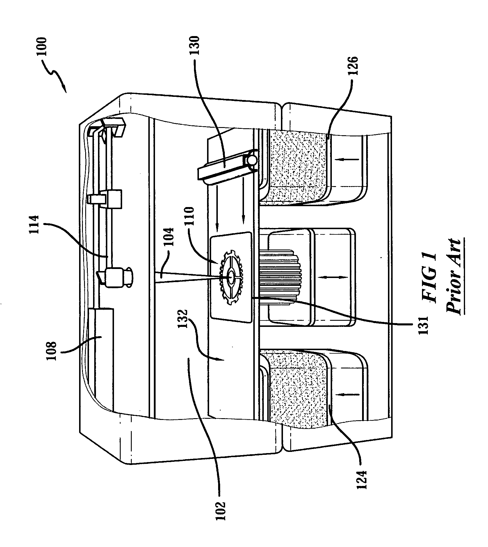
[0026]FIG. 1 illustrates, by way of background, a rendering of a conventional selective laser sintering system currently sold by 3D Systems, Inc. of Valencia, Calif. FIG. 1 is a rendering shown without doors for clarity. A carbon dioxide laser and its associated optics is shown mounted in a unit above a process chamber that includes a powder bed, two feed powder cartridges, and a leveling roller. The process chamber maintains the appropriate temperature and atmospheric composition for the fabrication of the article. The atmosphere is typically an inert atmosphere, such as nitrogen. It is also possible to use a vacuum in the process chamber.

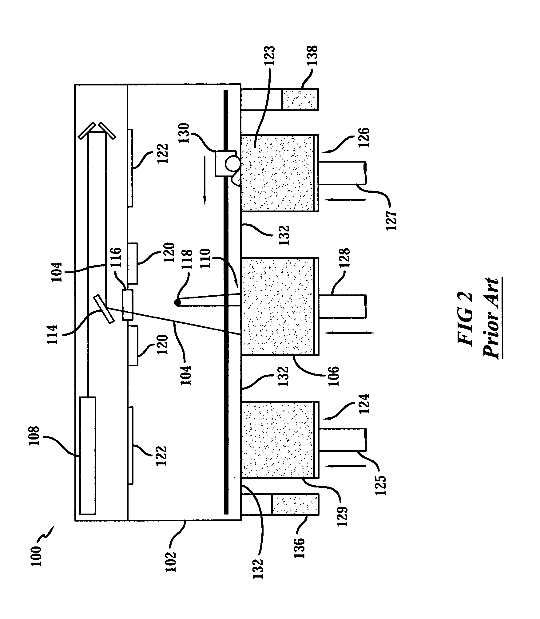
[0027] Operation of this conventional selective laser sintering system 100 is shown in FIG. 2 in a front view of the process with the doors removed for clarity. A laser beam 104 is generated by laser 108, and aimed at target surface or area 110 by way of scanning system 114 that generally includes galvanometer-driven mirrors which deflect the las...


PUM

PropertyMeasurementUnit
angleaaaaaaaaaa
angleaaaaaaaaaa
angleaaaaaaaaaa

Abstract

A method of obtaining uniform thermal distribution imaging in a thermally initiated and thermally based laser sintering process whereby a three-dimensional object is formed layer-by-layer in which the scanning sequences in successive layers is varied to more uniformly control the build up of heat within a three-dimensional object being formed. An improved method of image scanning multiple parts in a single build process is also employed.

Description

BACKGROUND OF THE INVENTION [0001] 1. Field of the Invention [0002] This invention relates to the field of freeform fabrication, and more specifically is directed to the fabrication of three-dimensional objects by selective laser sintering utilizing an improved scanning technique. 2. Description of the Related Art [0003] The field of freeform fabrication of parts has, in recent years, made significant improvements in providing high strength, high density parts for use in the design and pilot production of many useful articles. Freeform fabrication generally refers to the manufacture of articles directly from computer-aided-design (CAD) databases in an automated fashion, rather than by conventional manual machining of prototype articles according to engineering drawings. As a result, the time required to produce prototype parts from engineering designs has been reduced from several weeks to a matter of a few hours. [0004] By way of background, an example of a freeform fabrication tec...

Claims


Application Information

Patent Timeline
Patent Type & Authority Applications(United States)
IPC IPC(8): B29C35/08B29C41/02B29C67/00
CPCB29C67/0077B29C64/153B29C64/182
Inventor NEWELL, KENNETH J.GEVING, BRADLEY D.
Owner 3D SYST INC
Why Eureka
Try Eureka