Efficient current monitoring for DC-DC converters

a converter and current monitoring technology, applied in the direction of pulse technique, multi-input and output pulse circuit, instruments, etc., can solve the problems of short circuit operation time of current limiting circuit, etc., to avoid degrading input signals, reduce the size of the inductor, and speed up the decision circuit

Inactive Publication Date: 2005-11-03
TEXAS INSTR INC
View PDF7 Cites 6 Cited by
  • Summary
  • Abstract
  • Description
  • Claims
  • Application Information

AI Technical Summary

Benefits of technology

[0012] The present invention has fewer switching devices at the input of the circuit where it is critical to have quiet circuitry to avoid degrading the input signals. The comparator of the present invention utilizes a technique novel to and optimized for current trip monitoring providing a faster decision circuit, allowing a reduction of the size of an inductor needed at th

Problems solved by technology

Without over current monitoring, both the switching regulator itself and the circuits powered by the regulator may overheat and collapse when there is

Method used


Image

  • Efficient current monitoring for DC-DC converters
  • Efficient current monitoring for DC-DC converters
  • Efficient current monitoring for DC-DC converters

Examples


Embodiment Construction

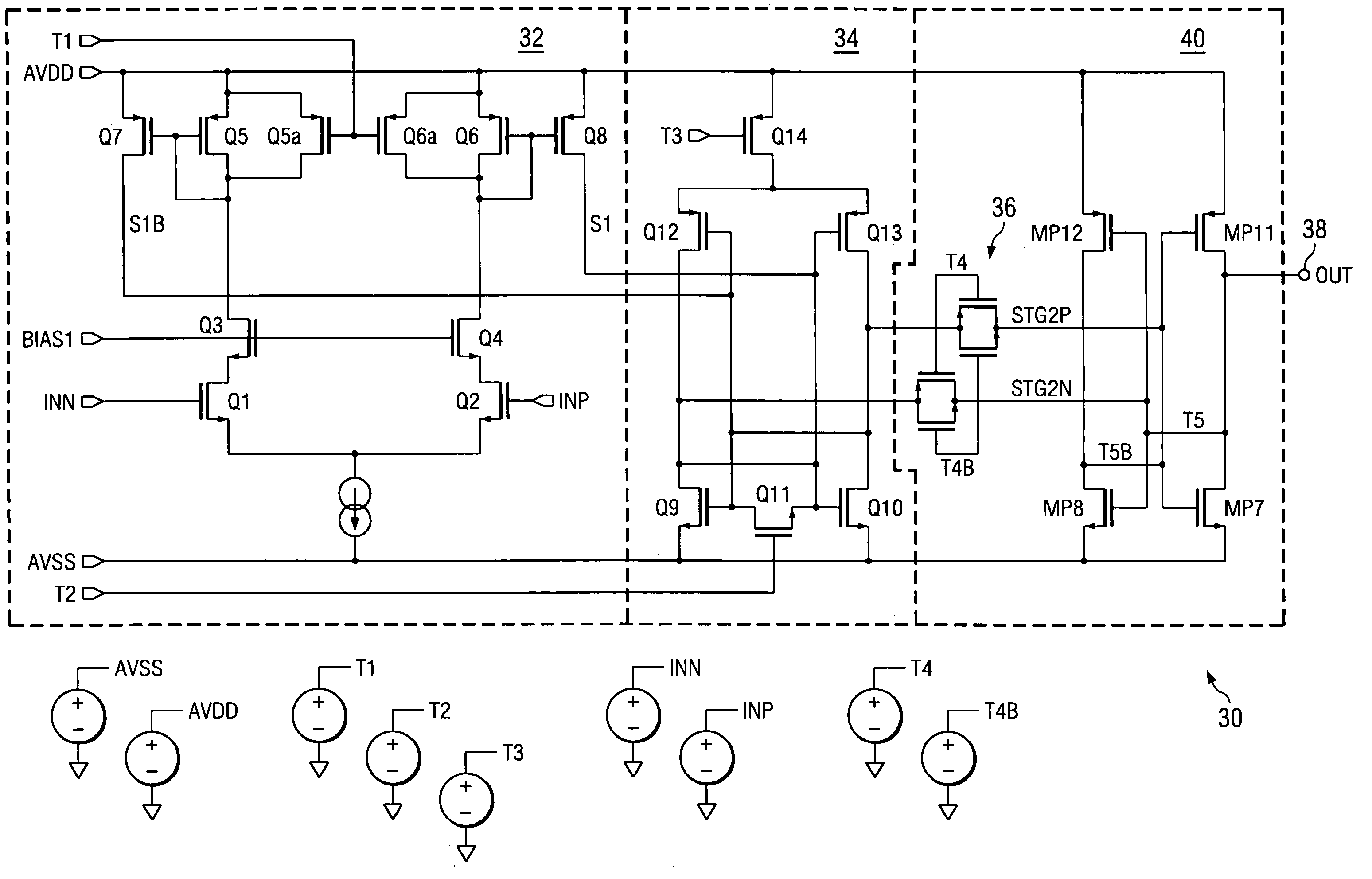
[0019] The present invention comprises an improved “track and latch” decision circuit providing over-current monitoring, whereby the preamplifier and the latch stage are advantageously independently controlled, with one preferred embodiment of the invention shown as a comparator circuit 30 in FIG. 4.

[0020] Comparator 30 has two voltage inputs, inp and inn, input to the comparator's preamplifier stage 32 operating as a first stage. One input is formed from the current sensing element, and the other input represents the reference current trip point threshold voltage. A differential current mirror OTA, comprising transistors Q1-Q8 along with a current source bias, is used in the preamplifier stage 32 of a comparator 30 to magnify the difference between the inputs inn and inp. Diode connected load transistors Q5, Q6 are in saturation and keep the node voltage at the drain of the input transistors, Q1 and Q2, of the first stage 32 fairly stationary, allowing high speed operation to the ...


PUM


Abstract

The present invention achieves technical advantages as a current monitoring circuit for DC-DC switching converters, including a track and latch comparator circuit (30) having a preamplifier (32) that is controlled independently of a latch circuit (34). Advantageously, the comparator is small and operates very fast and with improved sensitivity. For example, the preamplifier circuit is disabled when the latch stage is making its decision to avoid noise and input disturbances from affecting the latch stage. This selective disabling feature speeds up the signal processing of the comparator and allows it to work in parallel with other circuits. The latch stage can make its decision later, regardless of any further activity at the inputs of the comparator.

Description

FIELD OF THE INVENTION [0001] The present invention is generally related to DC-DC switching converters, and more particularly to current monitoring of these converters. BACKGROUND OF THE INVENTION [0002] Current monitoring and overcurrent trip circuits are typically used in high current voltage regulation IC's, including DC-DC switching converters. These circuits protect the IC, and / or the other circuits to which the regulator is supplying current, in applications such as computers, communications, and industrial machinery. Without over current monitoring, both the switching regulator itself and the circuits powered by the regulator may overheat and collapse when there is too much current being supplied to the load. [0003] In a conventional DC-DC converter, a switching transistor (switcher) is turned ON to pass a noisy input voltage to the output as a quiet, well regulated output voltage that is sourcing a large current. This current may be monitored a number of ways. A typical curr...

Claims


Application Information

Patent Timeline
IPC IPC(8): G01R19/165H03K5/22H03K5/24
CPCG01R19/16519H03K5/2481G01R19/16571G01R19/16552
Inventor WU, DOLLY Y.
Owner TEXAS INSTR INC
Why Eureka
Try Eureka