Gas treatment apparatus
- Summary
- Abstract
- Description
- Claims
- Application Information
AI Technical Summary
Benefits of technology
Problems solved by technology
Method used
Image

Examples
first embodiment
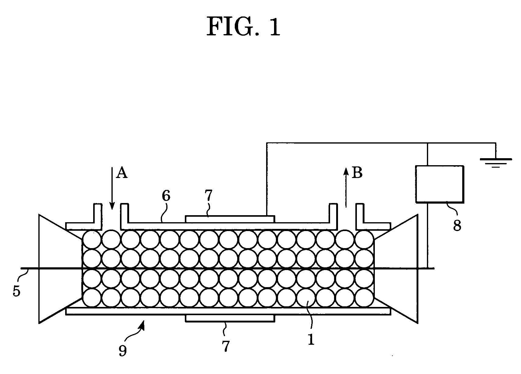
[0018] In a gas treatment apparatus for treating gas that contains target substances with non-thermal plasma according to a first embodiment, dielectric particles are produced by covering ferroelectric cores with adsorbent that supports a metal catalyst. The dielectric particles are disposed in a space between two electrodes so as to have air gaps therebetween. As a result, electrical discharge can be efficiently performed at a low field intensity. Moreover, the adsorbent can retain the target substances in the space where the electrical discharge takes place for a longer time. In addition, the metal catalyst and the plasma can improve the treatment performance.
[0019] The target substances include VOCs, nitrogen oxides, and foul-smelling substances. However, the target substances are not limited to these substances, and the present invention is intended for any gaseous substance.
[0020] A gas treatment apparatus for treating gas that contains target substances with non-thermal plas...
second embodiment
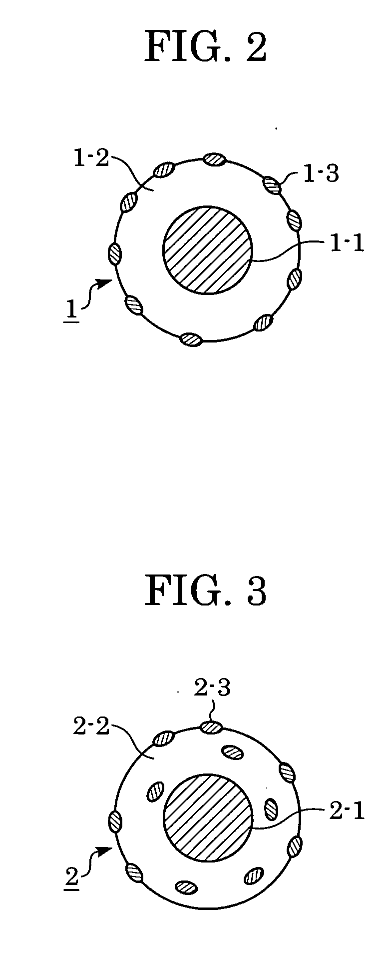
[0026] A gas treatment apparatus according to a second embodiment has the same structure as that in the first embodiment except that dielectric particles are produced by covering ferroelectric cores with a mixture of adsorbent and a metal catalyst.
[0027]FIG. 3 shows one of the dielectric particles 2 that are disposed in the space between the electrodes. The dielectric particle 2 shown in FIG. 3 is composed of a ferroelectric core 2-1, and adsorbent 2-2 covering the ferroelectric core 2-1, the adsorbent 2-2 having metal catalytic sites 2-3 at the interior and the surface of the adsorbent 2-2.
[0028] The dielectric particles according to the first embodiment and the second embodiment are preferably ferroelectric. The relative dielectric constant is preferably between 500 and 10,000 to suppress the discharge threshold voltage.
[0029] The adsorbent according to the first embodiment and the second embodiment is preferably at least one of activated carbon, silica, alumina, and zeolite.
[...
example 1
Dielectric Particles Having Adsorbent Supporting a Metal Catalyst
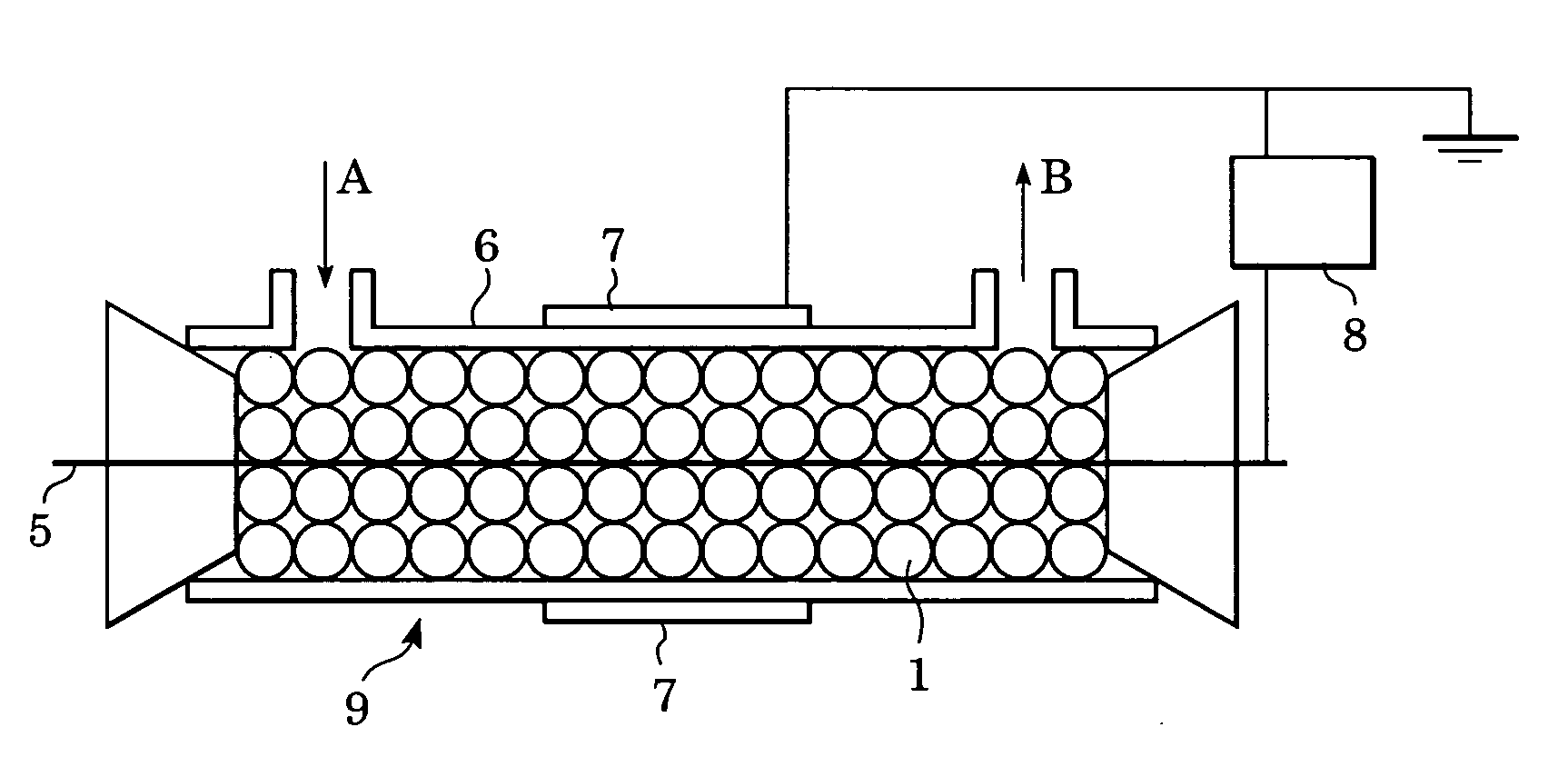
[0034] Performance of the treatment of the target substances in the gas treatment apparatus shown in FIG. 1 was determined. The wire electrode 5 was a tungsten wire 0.5 mm in diameter, the ground electrode 7 was an SUS steel cylinder 12 mm in diameter and 13 mm in length, and the barrier 6 disposed in the SUS steel cylinder was made of quartz glass 1 mm in thickness. The dielectric particles 1 were each 3 mm in diameter, and were composed of spherical barium titanate (having a relative dielectric constant of 1,600) covered with zeolite that supported palladium. The dielectric particles 1 were disposed in the space between the electrodes.
[0035] The gas A to be treated was air-based gas (mainly composed of nitrogen and oxygen) containing 10 ppm of ammonia, and was circulated through a reactor, i.e. the gas treatment apparatus 9, at a rate of 10 L / min. Subsequently, a voltage of 7 kV was applied between the wire electro...
PUM
 Abstract
Description
Claims
Application Information
 - R&D
- Intellectual Property
- Life Sciences
- Materials
- Tech Scout
- Unparalleled Data Quality
- Higher Quality Content
- 60% Fewer Hallucinations
Browse by: Latest US Patents, China's latest patents, Technical Efficacy Thesaurus, Application Domain, Technology Topic, Popular Technical Reports.
© 2025 PatSnap. All rights reserved.Legal|Privacy policy|Modern Slavery Act Transparency Statement|Sitemap|About US| Contact US: help@patsnap.com