
Multiple meander strip monopole antenna with broadband characteristic

a broadband characteristic and antenna technology, applied in the field of antennas, can solve the problems of distortion in transmitted and received signals, hardly satisfying the requirements of small antennas,

Inactive Publication Date: 2005-11-10
AJOU UNIV IND ACADEMIC COOP FOUND
View PDF4 Cites 13 Cited by
  • Summary
  • Abstract
  • Description
  • Claims
  • Application Information

AI Technical Summary

Benefits of technology

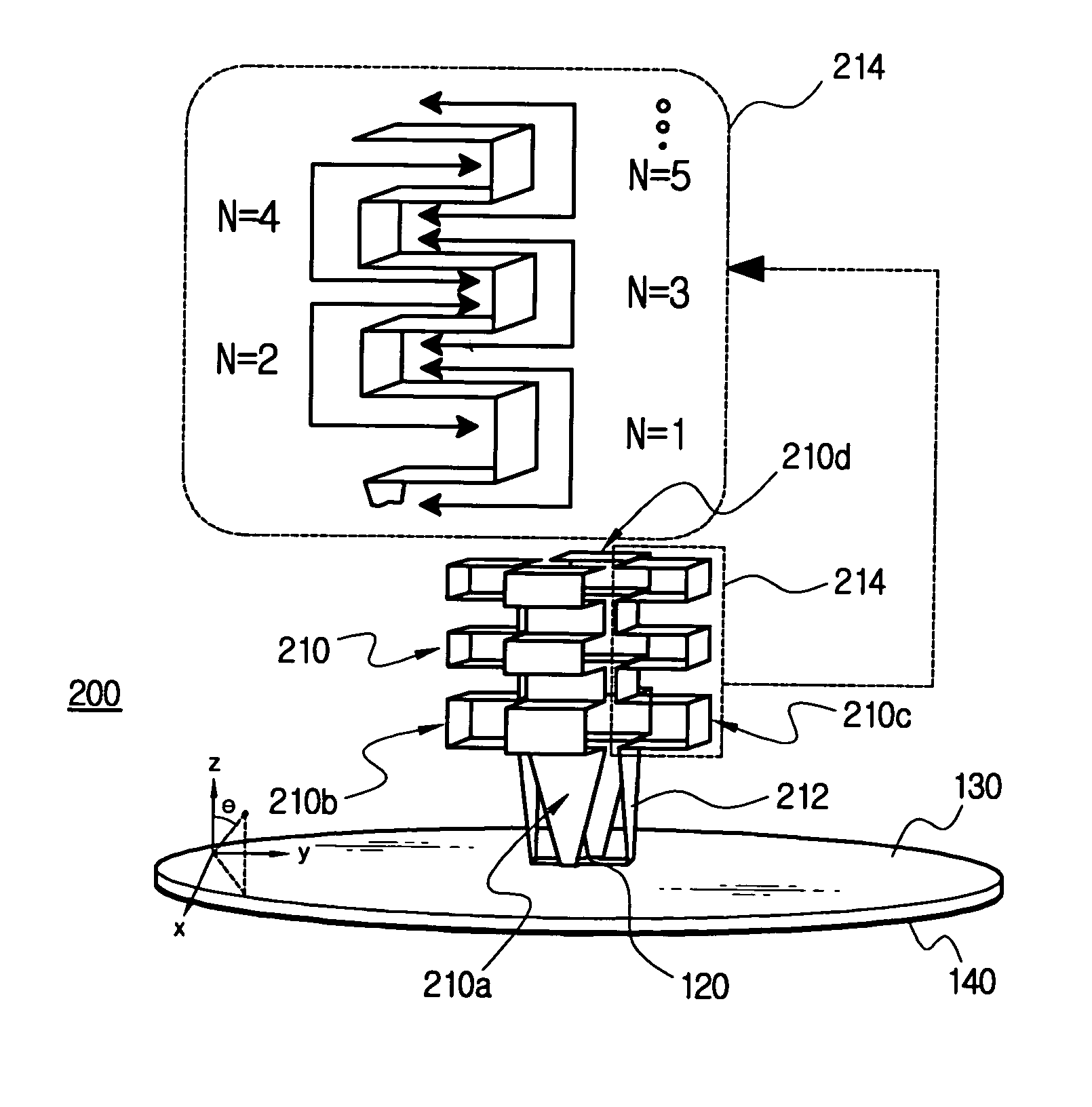
[0009] The above-described antenna, in particular, the meander strip section is preferred to include a multi-stepped strip section, in which at least one conductor strip having a ‘’ shape is connected, in a meander fashion, to the end of the ‘’-shaped conductor strip. This antenna structure can be called a typical multiple meander strip monopole antenna structure in that it is a multiple-meandered structure in which a ‘’-shaped strip is connected repeatedly one above the other. It has a characteristic that the bandwidth increases as the number of meandering increases. This antenna structure can be used for designing an antenna having a wideband characteristic from 2.9 GHz to 10.82 GHz, which meets the UWB communication band from 3.1 GHz to 10.6 GHz. The excellent omni-directional radiation pattern of this antenna is suitable for a wireless LAN or a wireless personal area network (WPAN), or the like, which requires the omni-directional communication.
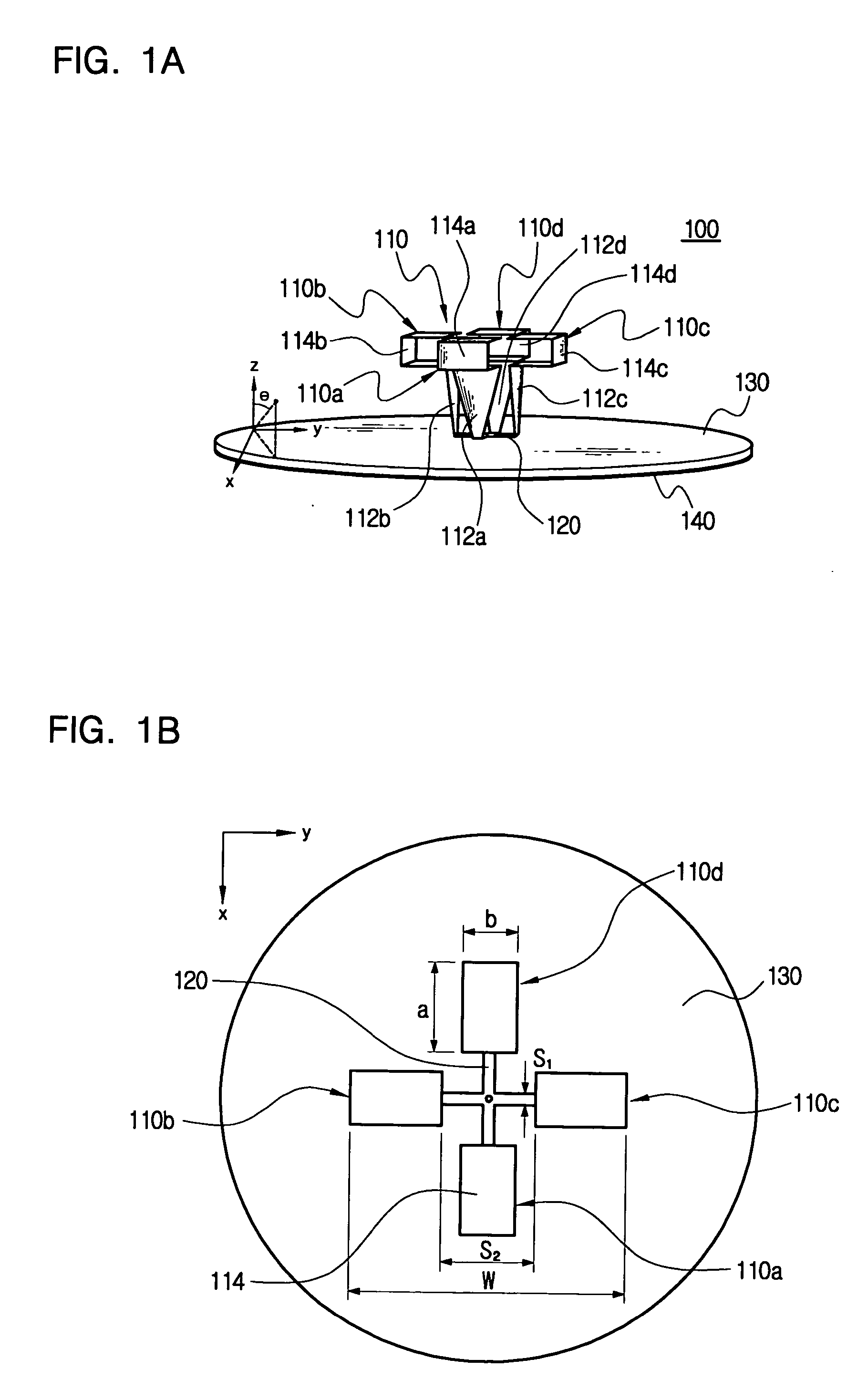
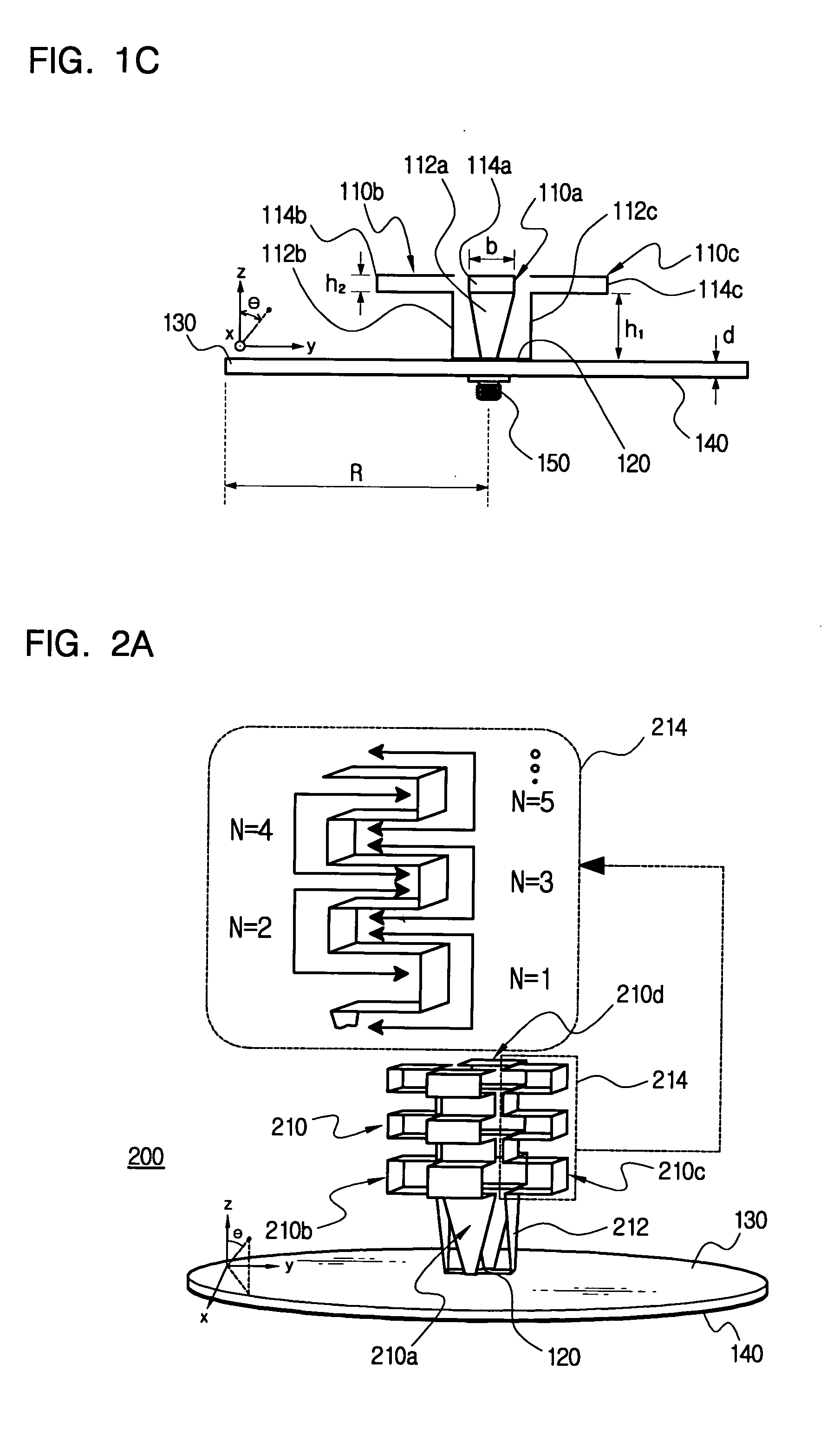
[0011] It is preferable that the radial cross-strip includes X branch-strips each having a same line-width and length and being disposed in equiangular intervals of 360° / X. Preferably, the vertical strip section has a tapered structure, in which its width is progressively widened upwardly for an impedance matching. The tapered structure of the vertical strip section alleviates the impedance variation with the frequency, so that it contributes to obtain the wideband characteristic. In addition, in order to minimize a return loss through an impedance matching in the above antenna structure, it is preferable that the total length of the vertical strip section and the meander strip section is λ0 / 4, where λ0 is wavelength corresponding to a desired matching frequency. It is also preferable that a ratio of the height of the multiple radiator to the λ0 / 4 length of a starting frequency is less than 60%. This is, the lower height is more advantageous for the miniaturization of antenna.
[0013] The circular grounding conductor plate is advantageous in that a current flow in the grounding conductor plate can be uniform in all directions, thereby reducing the cross polarization and strengthening the characteristic of the omni-directional radiation pattern.

Problems solved by technology

However, a biconical antenna, a horn antenna, and a reflector antenna are relatively large in their size, so that they can hardly satisfy the requirements for small antennas.
A spiral antenna and a log periodic antenna cause a dispersion due to the radiation time difference between a low and high frequency with respect to an impulse signal composed of wideband frequency signals, not a narrow band sinusoidal wave, and thus it leads to a distortion in the transmitted and received signal.

Method used


Image

  • Multiple meander strip monopole antenna with broadband characteristic
  • Multiple meander strip monopole antenna with broadband characteristic
  • Multiple meander strip monopole antenna with broadband characteristic

Examples


Embodiment Construction

[0026] The preferred embodiments of the invention will be hereafter described in detail with reference to the accompanying drawings.

[0027]FIGS. 1a, 1b and 1c are respectively a perspective view, a plan view and an elevational view showing a basic structure of a multiple meander strip monopole antenna according to the first embodiment of the invention, in which the antenna of the invention is denoted by a reference numeral 100. Referring to FIGS. 1a, 1b and 1c, the structure and operational principle of the antenna according to the first embodiment are described. The antenna 100 of the invention has a folded multi-strip monopole antenna structure, in which an end portion of a vertical strip is bent into a ‘’-shape and, therefore, an overall antenna height can be reduced. In addition, an inductance component dominant in a narrowband monopole antenna can be compensated by a capacitance component built up between parallel strips so that the bandwidth can be significantly improved.

[002...


PUM


Abstract

Disclosed is a multiple meander strip monopole antenna, which can have a broad bandwidth and easily miniaturize the antenna by using a meander structure. A grounding conductor plate is coupled to the under face of a dielectric base plate. A radial cross-strip is disposed symmetrically at the center of the upper surface of the dielectric base plate. Each radiating member of a multiple radiator is connected to the end portion of each corresponding branch of the radial cross-strip and stands substantially perpendicular to the base plate. Each radiating member is composed of a vertical strip section having a tapered structure, in which its width is progressively widened upwardly for an impedance matching and at least one meander strip section connected integrally to the upper end of the vertical strip section. When a feeding is carried out at the center of the radial cross-strip, a signal radiated from the multiple radiator is cancelled out in the axial direction of θ=0° and a radiation gain is increased as θ increases, thereby providing a conical beam radiation pattern. A broad bandwidth from 2.9 GHz to 10.85 GHz can be achieved and an excellent monopole radiation pattern having the same gain in all directions can also be achieved.

Description

BACKGROUND OF THE INVENTION [0001] 1. Field of the Invention [0002] The present invention relates to an antenna, more particularly to a folded multi-strip monopole antenna, in which it can be miniaturized by reducing the height thereof. [0003] 2. Description of the Related Art [0004] Recently, researches have been extensively made in order to develop a technology related to an ultra wideband (UWB) communication. The UWB communication is regarded as a core technology in the next generation wireless communication. The UWB communication does not use a carrier wave, which is used to transmit a base band signal in a general wireless communication system. Instead, it uses a low power pulse having a signal time slot of only one nanosecond to a few picoseconds. It transmits a low power signal over a broad frequency band, so that the power consumption is less than the conventional systems. It shares the frequency band used by the conventional narrowband systems, without any separate allocati...

Claims


Application Information

Patent Timeline
Patent Type & Authority Applications(United States)
IPC IPC(8): H01Q13/08H01Q1/36H01Q5/00H01Q9/42H01Q21/20
CPCH01Q1/36H01Q21/205H01Q9/42H01Q13/08
Inventor PARK, IKMOLEE, YUN HO
Owner AJOU UNIV IND ACADEMIC COOP FOUND
Learn More