Optical transmission/reception module

a technology of optical transmission and reception module, applied in the field of optical transmission/reception module, can solve the problems of difficult acceleration and difficult miniaturization, and achieve the effect of increasing the mounting density and large-scale integration of optical transmission devi

Inactive Publication Date: 2005-11-10
PANASONIC CORP
View PDF0 Cites 8 Cited by
  • Summary
  • Abstract
  • Description
  • Claims
  • Application Information

AI Technical Summary

Benefits of technology

[0010] Another purpose of the present invention is to provide an optical transceiver module wherein the electric cross talk and the optical cross talk are small and acceleration is possible.
[0023] This construction allows the length of the electric circuit substrate in the direction of the optical axis to be shortened and also allows the directions of the flexible cables of the transmission section optical system and the receiving section optical system to match with each other, and thereby, the attachment / detachment of the optical module is facilitated. In addition, the off-position generated to the rotational direction of the LD can package can be easily absorbed.

Problems solved by technology

However, miniaturization was difficult because the optical axis adjustment is complicated and the rigid metallic cubicle 66 which retains the lens optical system is required.
However, since high-precision processing of the V-shaped groove and the optical waveguide 72 is required, the components are expensive, and at the same time, because the laser diode 75 and the photo diode 76 are allocated in proximity to each other, the electric and optical cross talks were large, and thus, acceleration was difficult.

Method used


Image

  • Optical transmission/reception module
  • Optical transmission/reception module
  • Optical transmission/reception module

Examples


first embodiment

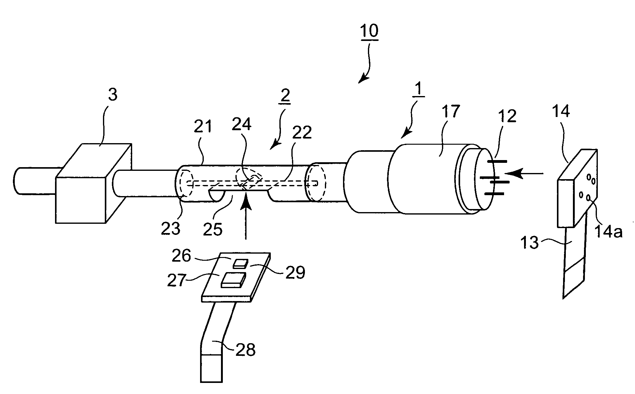
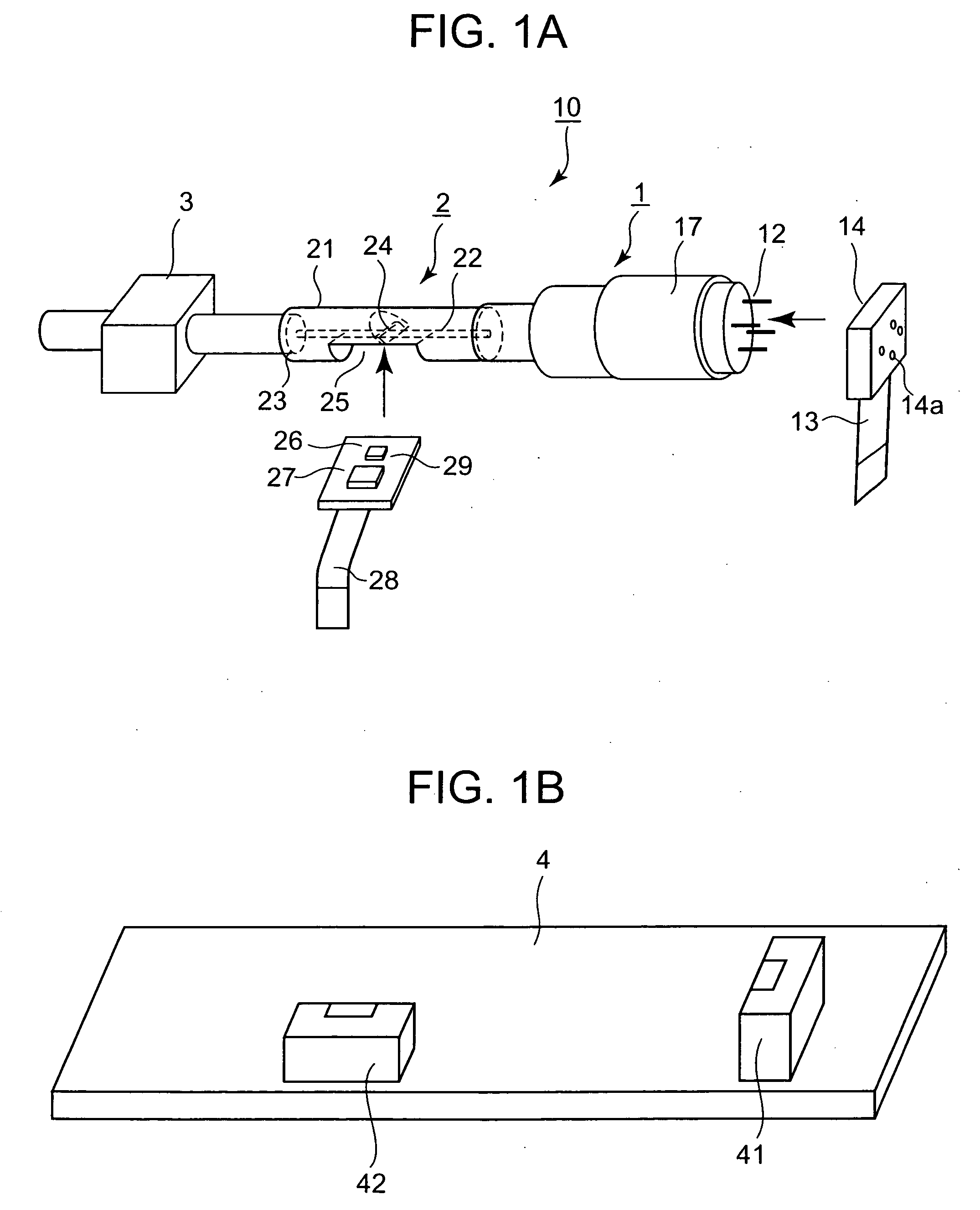
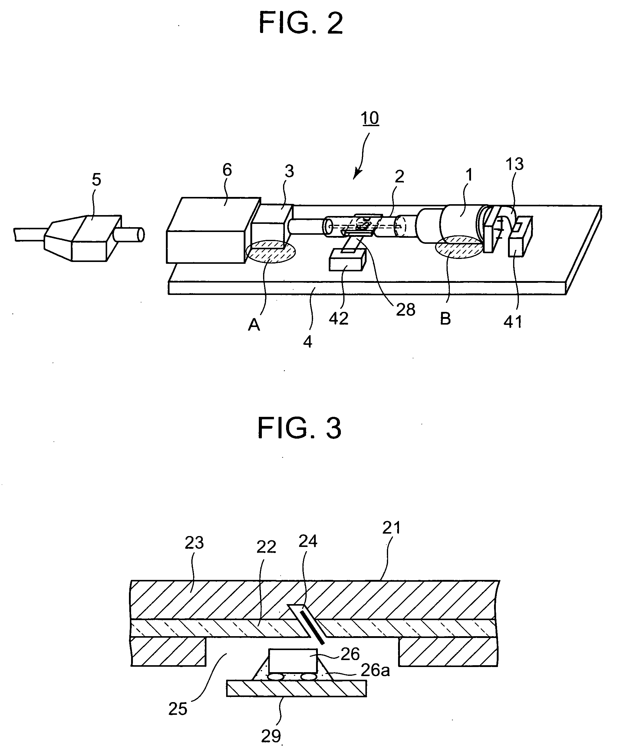
[0034]FIG. 1A is a perspective view showing the optical connection condition of the major elements is a optical transceiver module according to the present invention; FIG. 1B is a perspective view of a circuit substrate wherein the major elements shown in FIG. 1A are mechanically fixed and electrically connected; FIG. 2 is a perspective view showing the connection and fixing conditions of each element shown in FIGS. 1A and 1B; and FIG. 3 is a sectional view showing the detailed construction of the transmission section optical system shown in FIGS. 1A and 1B.

[0035] In each of these figures, the optical transceiver module, shown in its entirety in Reference No. 10, comprises a transmission section optical system 1, a receiving section optical system 2, and an optical I / O optical receptacle 3 which are mutually connected optically.

[0036] Of them, the transmission section optical system 1 comprises a LD can 11 with a lens which comprises a laser and an optical fiber or an optical waveg...

second embodiment

[0044] Thus, the length of the signal input terminal to the transmission section optical system 1 can be minimized, and the high frequency characteristics can be enhanced. Furthermore, deviation in the rotational direction to the optical axis of the LD can 11 can be absorbed easily by arranging the leading direction of the electric signal input lead wire 12 of the LD can 11 and the extension direction of the signal line of the flexible cable 13 to be almost vertical. In addition, the substrate 15 with the LD flexible cable in the transmission section optical system 1 can be assembled so as to be parallel with the substrate 29 with the flexible cable in the receiving section optical system 2, and thereby, the mounting of the optically connected optical module on the circuit substrate 4 can be facilitated, and the length of the substrate in the direction of the optical axis can be minimized.

third embodiment

[0045]FIG. 5 is a perspective view showing the construction in the optical transceiver module according to the present invention. In this embodiment, the afore-mentioned LD can 11 is determined to be the transmission section optical system 1, one end of the optical fiber 21 in the afore-mentioned receiving section optical system 2 is connected to the transmission section optical system 1, the optical fiber pig tail is connected to the other end of the optical fiber 21, and the pig tail-type fiber pig tail 7 is connected, to construct the optical transceiver module.

[0046] According this third embodiment, stress applied at the time of attachment / detachment of the optical connector will cease to affect the transmission section optical system 1 and the receiving section optical system 2. In addition, when the transmission section optical system 1 and the receiving section optical system 2 are simultaneously fixed rigidly to the circuit substrate or the like, the generation of any stress...


PUM


Abstract

A small-sized optical transceiver module, wherein any stress attributable to the differences in coefficient of thermal expansion between a transmission section optical system, a receiving section optical system, and the components which integrate and fix them and the like is not applied therebetween, and which is not influenced by any stress at the time of attachment / detachment of the optical connector is disclosed. The optical transceiver module is one wherein the transmission section optical system 1 which comprises a laser diode and an optical fiber or an optical waveguide optically connected to the laser diode and of which the electric input terminal of the laser diode is a flexible cable, a receiving section optical system 2 which comprises a photo diode and an optical fiber or an optical waveguide optically connected to the photo diode and of which the electric output terminal of the photo diode is a flexible cable, and an optical I / O optical receptacle 3 are optically connected, mechanically integrated and fixed, and the two flexible cables are spatially spaced out and disposed.

Description

TECHNICAL FIELD [0001] The present invention relates to an optical transceiver module used for optical fiber communication and the like. BACKGROUND ART [0002] Optical fiber communication which can transmit large volumes of information at a high-speed with low-loss in place of a metallic cable is drawing attention, and in recent years, high functionality, together with the price-reduction and speed-acceleration of an optical device, has become increasingly required. Although, as one example, the development of an optical communications system which realizes an up-and-down optical bidirectional transmission in different wavelengths using one optical fiber has been advanced, the optical module in this optical communications system requires a technology that integrates a laser diode, a photo diode, a wavelength division, a multiplexing functional part, and the like. [0003] Described below are two typically conventional optical transceiver modules. FIG. 6 is a first configuration example...

Claims


Application Information

Patent Timeline
Patent Type & Authority Applications(United States)
IPC IPC(8): G02B6/42
CPCG02B6/421G02B6/4246G02B6/4214
Inventor TOHGOH, HITOMAROASANO, HIROAKIUNO, HITOSHIKOBAYASHI, MASAKIITABASHI, NOBUTAKAAKIYA, NOBUYUKI
Owner PANASONIC CORP
Why Eureka
Try Eureka