Method and apparatus for tempering gaseous and/or liquid media in transportation vehicles, particularly in aircraft

Inactive Publication Date: 2005-11-17
AIRBUS OPERATIONS GMBH
View PDF32 Cites 21 Cited by
  • Summary
  • Abstract
  • Description
  • Claims
  • Application Information

AI Technical Summary

Benefits of technology

[0023] A defined and substantially low-delay tempering even of larger volume flows of the fluid in the area of a fluid outlet is achievable without excessive loading of the electrical on-board power supply of the transportation vehicle because, according to the inventive method and / or using the inventive apparatus, thermal energy is stored in at least one thermochemical reservoir (e.g. during periods of low electrical demand), and then (e.g. during a period of high electrical demand) the thermal energy from the thermochemical reservoir or reservoirs is supplied to or withdrawn from a gaseous and / or liquid fluid supplied via the fluid reservoir and / or the feed inlet, whereby the supply or the withdrawal of the thermal energy is varied by means of the control and regulating arrangement for the adjusted setting of a temperature of the fluid provided at the fluid outlet.
[0025] Thus, for example, water withdrawn from a water reservoir or a water supply or feed line can be quickly warmed in a first thermochemical reservoir, whereby the water is either delivered directly to a fluid outlet and / or is first mixed with the water in the water reservoir before being delivered away to the fluid outlet. In this regard, the warming in the first thermochemical reservoir is achieved through the introduction of hydrogen into this reservoir, which is given off from a second thermochemical reservoir, to which heat had been supplied preferably at a lower temperature level over a longer time duration.
[0027] Through a simple and rapidly possible switching-over, for example by means of known electrically operable valves, the through-flow of the water can be switched between the first and the second thermochemical reservoir, so that nearly delay-free temperature changes of the water in the area of the fluid outlet are realizable. An additional advantage of the apparatus is that these temperature changes in the course of the tempering are possible without an excessive supply of electrical energy.
[0029] Simultaneously, through the desorption of hydrogen in a second thermochemical reservoir, heat energy can be (chemically) accumulated at a low temperature level over a longer time in a second thermochemical reservoir, and can again be given off at a high temperature level for a shorter time in a first thermochemical reservoir, e.g. during peak load times of the electrical on-board power supply, and can, for example, be used for the warming of water. Parallel to this, a cooling of the water in the second thermochemical reservoir is also possible if necessary. Simultaneously, through the operation of the apparatus according to the invention, an evening-out or smoothing of the electrical load curve of the electrical on-board power supply is also achieved.

Problems solved by technology

This leads to very high load peaks in the electrical on-board power supply of the transportation vehicle, e.g. an aircraft, especially in the time periods in which a high demand for warm and hot water exists, for example at the meal times or in the early morning after the sleeping phase of a flight.
The higher power capacity design of the electrical on-board power supply generally also necessitates a significant increase of the weight, which is disadvantageous especially in aircraft, because thereby the operating range is reduced, for example.

Method used


Image

  • Method and apparatus for tempering gaseous and/or liquid media in transportation vehicles, particularly in aircraft
  • Method and apparatus for tempering gaseous and/or liquid media in transportation vehicles, particularly in aircraft

Examples


Embodiment Construction

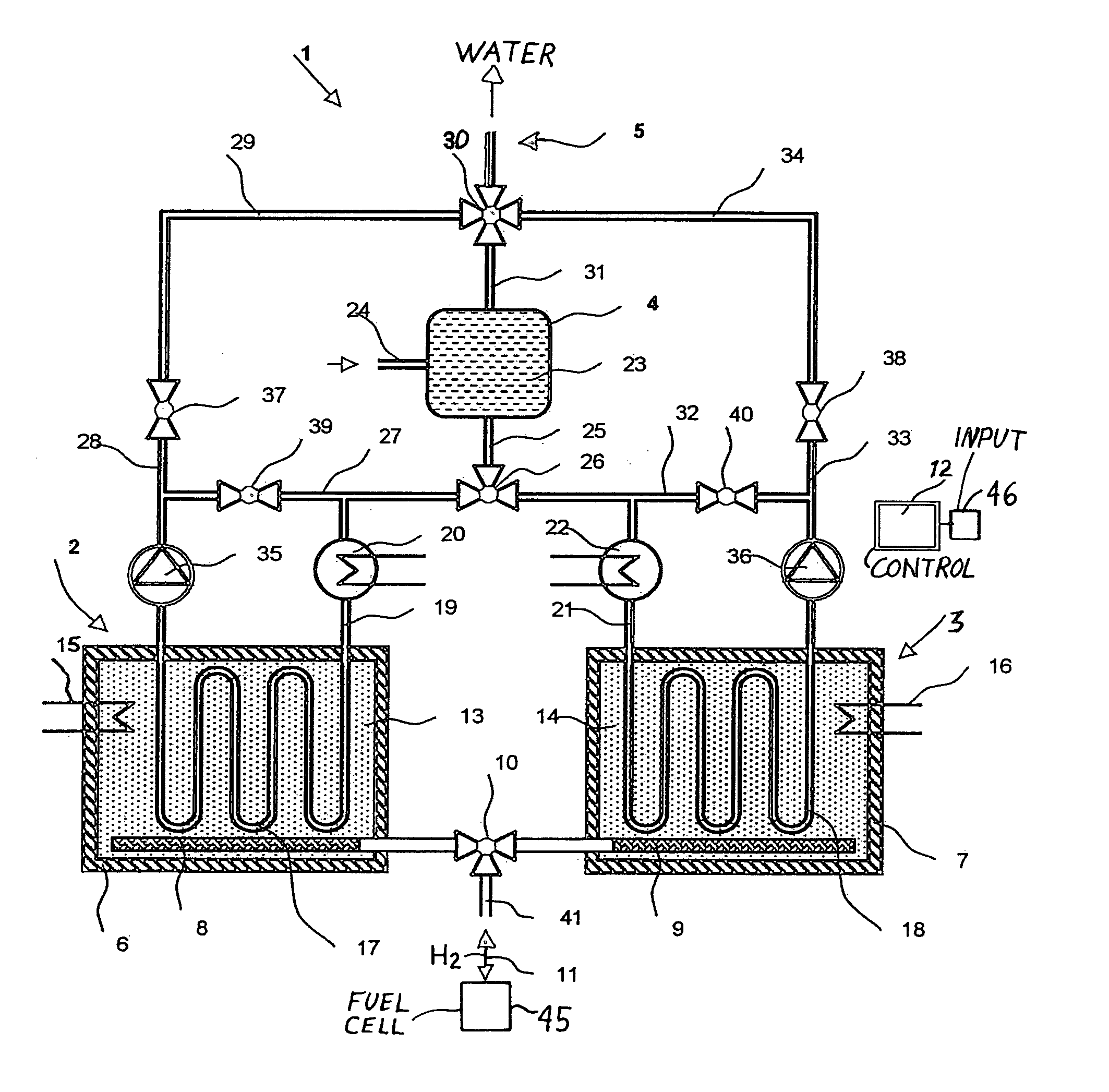
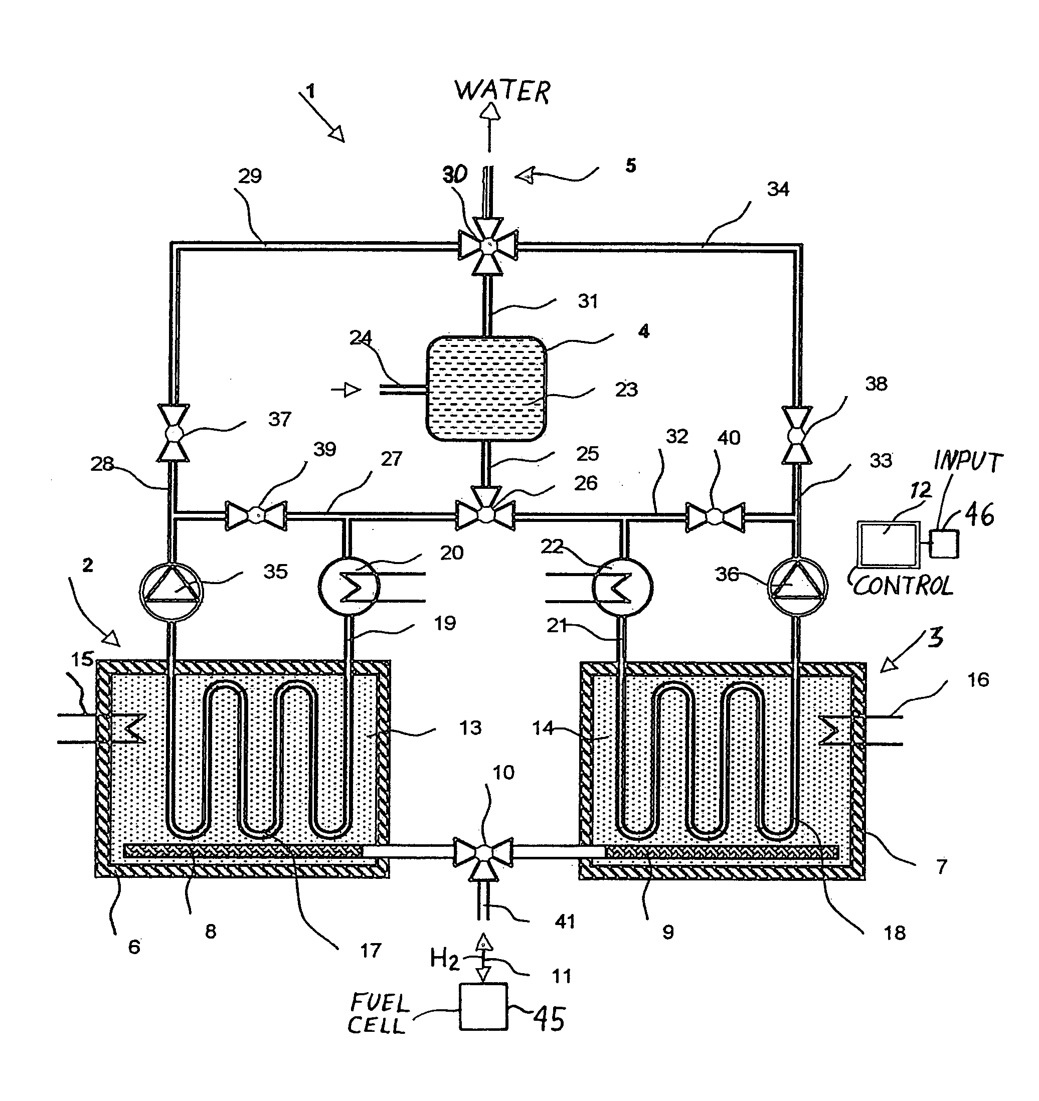
[0032] The single FIGURE shows an example embodiment of an apparatus 1 according to the invention for the tempering of gaseous and / or liquid fluids in transportation vehicles, especially in aircraft.

[0033] The apparatus 1 consists, among other things, of a first thermochemical reservoir 2, a second thermochemical reservoir 3, a fluid reservoir 4, as well as a fluid outlet 5.

[0034] The first thermochemical reservoir 2 comprises, among other things, a first container 6, and the second thermochemical reservoir 3 includes a second container 7. The first and the second containers 6, 7 can be provided with an additional thermal insulation, in order to minimize heat losses. Furthermore the containers 6, 7 are embodied to be pressure-resistant and gas-tight.

[0035] A first hydrogen distributor 8 is arranged within the first container 6, and correspondingly a second hydrogen distributor 9 is arranged in the second container 7. The hydrogen distributors may comprise perforated or porous pip...


PUM


Abstract

For example an aircraft includes a fluid tempering arrangement to supply a gaseous and / or liquid, heated and / or cooled, fluid such as water. At least one thermochemical reservoir is in heat exchange relation with a conduit system, having at least one valve and a controller that controls the transfer of heat between the fluid and the thermochemical reservoir to adjust the temperature of the fluid provided to an outlet. Preferably two interconnected thermochemical reservoirs respectively contain hydride-forming metals having different hydrogen sorption-desorption temperatures. A method involves supplying and chemically storing heat energy in at least one thermochemical reservoir, then performing a reverse reaction to release and transfer heat from at least one thermochemical reservoir to the fluid, preferably involving the sorption and desorption of hydrogen in respective hydride-forming metals in two reservoirs exhibiting different hydrogen reaction temperatures. Heat energy produced electrically during low electrical demand can be chemically stored and later released for heating the fluid during high electrical demand.

Description

CROSS-REFERENCE TO RELATED APPLICATION [0001] This U.S. Non-Provisional Application claims the benefit under 35 U.S.C. §119(e) of U.S. Provisional Application 60 / 600,061, filed on Aug. 9, 2004, the entire disclosure of which is incorporated herein by reference.PRIORITY CLAIM [0002] This application is based on and claims the priority under 35 U.S.C. §119 of German Patent Application 10 2004 019 790.3, filed on Apr. 23, 2004, the entire disclosure of which is incorporated herein by reference. FIELD OF THE INVENTION [0003] The invention relates to a method and an apparatus for tempering, i.e. heating and / or cooling, gaseous and / or liquid fluids in transportation vehicles, particularly in aircraft. BACKGROUND INFORMATION [0004] In transportation vehicles, especially on board of air vehicles such as aircraft or airplanes for example, apparatuses for the warming or heating of media, i.e. gaseous and / or liquid fluids, particularly water and / or air for example, are being increasingly emplo...

Claims


Application Information

Patent Timeline
IPC IPC(8): B64C1/00B64D11/02F28D20/00
CPCB64D11/02F28D20/003Y02T50/46Y02E70/30Y02E60/142Y02E60/14Y02T50/40
Inventor HOEHNE, MERLEHOEHNE, JOACHIMHEINRICH, HANS-JUERGEN
Owner AIRBUS OPERATIONS GMBH
Why Eureka
Try Eureka