Laser irradiation method and laser irradiation apparatus

Active Publication Date: 2005-11-17
SEMICON ENERGY LAB CO LTD
View PDF47 Cites 8 Cited by
  • Summary
  • Abstract
  • Description
  • Claims
  • Application Information

AI Technical Summary

Benefits of technology

[0012] It is an object of the present invention to provide a laser irradiation method and a laser irradiation apparatus which are suitable, for example, for crystallizing an amorphous semiconductor film and which can deliver a laser beam having homogeneous intensity distribution without causing bias in the energy intensity in reflection of bias in the intensity distribution of the original beam. It is to be noted that the present invention uses a cylindrical lens so as to facilitate the optical alignment with a configuration different from that disclosed in the Reference 1.
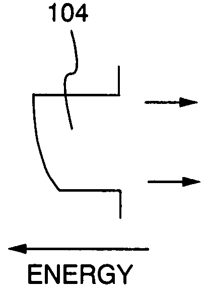
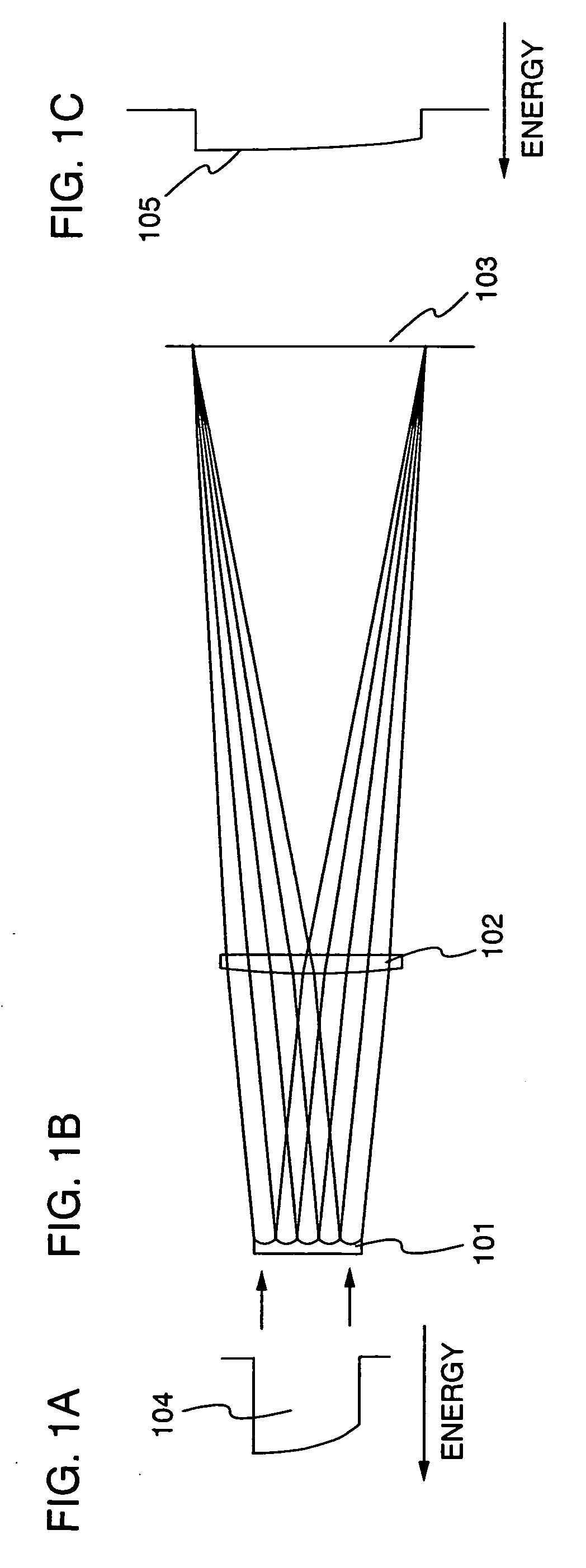
[0016] As a result, although the original beam has bias in the energy intensity distribution, the bias can be offset on the irradiation surface because the laser beams transmitted through the convex and concave cylindrical lens arrays are projected to the irradiation surface with their distribution inverted to each other. Therefore, according to the present invention, the intensity distribution having bias in one direction can be offset, thereby forming a linear laser beam with high homogeneity on the irradiation surface. Moreover, an optical system that is difficult to be affected by the fluctuation of the intensity distribution of the original beam can be constituted.

Problems solved by technology

Since the heat treatment is performed at high temperature, a glass substrate has a problem of being softened due to the heat, for example.
Despite the advantage mentioned above, the laser annealing has a problem of irradiation unevenness on a film because the intensity distribution of the linear laser beam fluctuates when the laser beam is scanned.
Therefore, when a display device with a driver and a pixel integrated (system-on-panel) is manufactured with the film having irradiation unevenness, the irradiation unevenness appears directly on the screen of the display device.
The irradiation unevenness causes a problem particularly when a display device with high accuracy and high characteristic, typically an EL display, is manufactured.
However, when the requirement is not satisfied, for example when the linear laser beam does not have homogeneous energy distribution in the major-axis direction (or longitudinal direction), it is difficult to perform laser processing all over the region in the major-axis direction within the optimum energy range.
As a result, it becomes impossible to process the entire surface of the substrate homogeneously, and thus the irradiation unevenness occurs.
However, with the increase of the number of divided beams, the interference between the divided beams become more remarkable, which may result in the appearance of the interference fringes on the irradiation surface.
Moreover, when a cylindrical lens array is manufactured with cylindrical lenses each having large aspect ratio between its width and length, enough strength and lens accuracy are difficult to achieve; therefore, the desired beam is difficult to obtain.
For this reason, actually, it is difficult to increase the number of divided beams more than the predetermined number in the laser irradiation.
Although the number of divided beams is increased, the linear laser beam has the intensity distribution with the bias in the major-axis direction in the same manner; therefore homogeneous processing is impossible.
Moreover, it has been known that the intensity distribution of the original beam may fluctuate due to thermal distortion of an element in the resonator.

Method used


Image

  • Laser irradiation method and laser irradiation apparatus
  • Laser irradiation method and laser irradiation apparatus
  • Laser irradiation method and laser irradiation apparatus

Examples


embodiment 1

[0059] The present invention is hereinafter described more specifically as taking an embodiment for manufacturing a TFT as an example. However, the present invention is not limited to this embodiment, but specified by the scope of claims. This embodiment describes a step of manufacturing a thin film transistor (TFT) with a laser irradiation apparatus of the present invention with reference to FIGS. 7A to 7D.

[0060] First, a base film 701 is formed over a glass substrate 700 having an insulating surface as shown in FIG. 7A. The glass substrate 700 may be, for example, a glass substrate such as barium borosilicate glass or alumino borosilicate glass, a quartz substrate, a SUS substrate, or the like. In addition, although a substrate made of flexible synthetic resin such as acrylic or plastic typified by PET (polyethylene terephthalate), PES (polyethylene sulfone), PEN (polyethylene naphthalate), or the like tends to be inferior to other substrates in point of the resistance against th...


PUM

PropertyMeasurementUnit
Energyaaaaaaaaaa
Distributionaaaaaaaaaa

Abstract

The present invention is to provide a laser irradiation technique for irradiating the irradiation surface with the laser beam having homogeneous intensity distribution using a cylindrical lens array without being affected by the intensity distribution of the original beam. A laser beam emitted from a laser oscillator is divided by two kinds of cylindrical lens arrays into a plurality of beams, which are two kinds of linear laser beams with their energy intensity distribution inverted each other, and the two kinds of linear laser beams are superposed in a minor-axis direction. This can form the linear laser beam having homogeneous intensity distribution on the irradiation surface.

Description

BACKGROUND OF THE INVENTION [0001] 1. Field of the Invention [0002] The present invention relates to a laser irradiation method and a laser irradiation apparatus which are suitable, for example, for crystallizing an amorphous semiconductor film and which can project a linear laser beam having homogeneous intensity distribution to an irradiation surface. More specifically, the present invention relates to a laser irradiation method and apparatus using a cylindrical lens which can form a laser beam having homogeneous intensity distribution and which can project the linear laser beam having homogeneous intensity distribution onto an irradiation surface without causing the linear laser beam to have bias in its intensity distribution in reflection of intensity distribution of an original beam. [0003] 2. Description of the Related Art [0004] Conventionally, a semiconductor device has been manufactured by crystallizing an amorphous silicon film generally through heat treatment or laser ann...

Claims


Application Information

Patent Timeline
IPC IPC(8): H01L21/20B23K15/00B23K15/10B23K26/073G02B27/09H01L21/336H01L29/786
CPCB23K15/0093B23K15/10B23K26/0732G02B27/0966G02B27/0927G02B27/0961B23K26/0738B23K2103/56B23K26/0608B23K26/0648G02B3/0062
Inventor TANAKA, KOICHIROOISHI, HIROTADA
Owner SEMICON ENERGY LAB CO LTD
Why Eureka
Try Eureka