Module for cooling semiconductor device

a semiconductor device and module technology, applied in the field of modules for cooling semiconductor devices, can solve the problems of large amount of heat generated, insufficient heat absorption of peltier devices (tec), and insufficient heat absorption of heat pipes. achieve the effect of improving cooling efficiency

Inactive Publication Date: 2005-11-24
FURUKAWA ELECTRIC CO LTD
View PDF16 Cites 131 Cited by
  • Summary
  • Abstract
  • Description
  • Claims
  • Application Information

AI Technical Summary

Benefits of technology

[0017] One object of the invention is to provide a heat sink for cooling a semiconductor element generating a large amount

Problems solved by technology

Since the microprocessor is densely integrated and processes computing and control at high speed, a large amount of heat is generated.
Furthermore, recently, since a semiconductor device processing high speed signal generates larger amount of heat, the above mentioned heat pipe does not fully cool the device.
However, there are the following problems in the conventional method in which the lower temperature side of the Peltier device is attached to the heat generating source while the higher temperature side of the Peltier device is attached to the heat sink.
When the heat from the heat generating source (for example, CPU) increases, the heat absorb

Method used


Image

  • Module for cooling semiconductor device
  • Module for cooling semiconductor device
  • Module for cooling semiconductor device

Examples


example 1

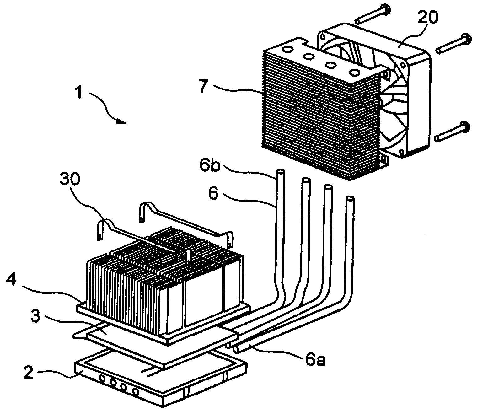
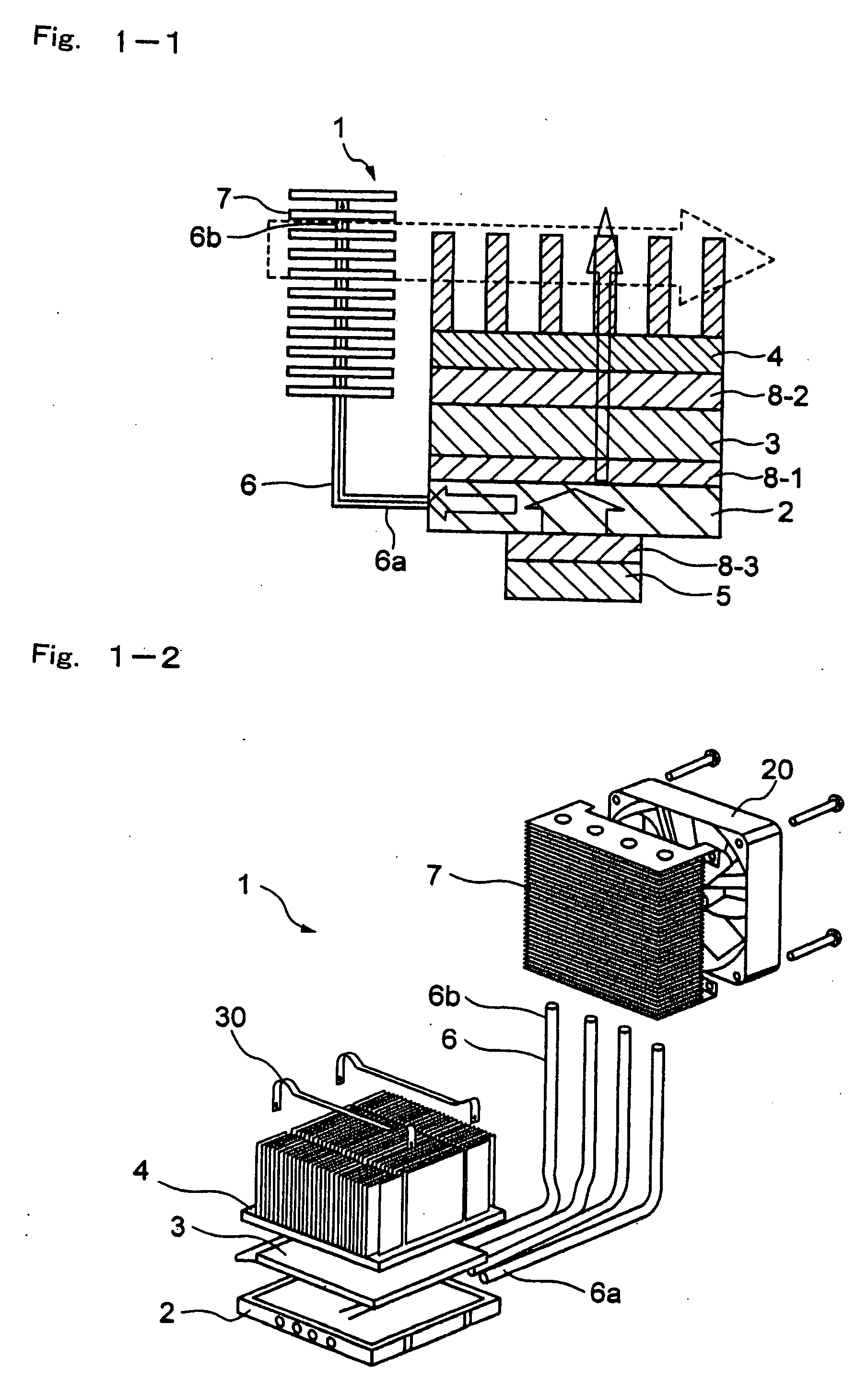
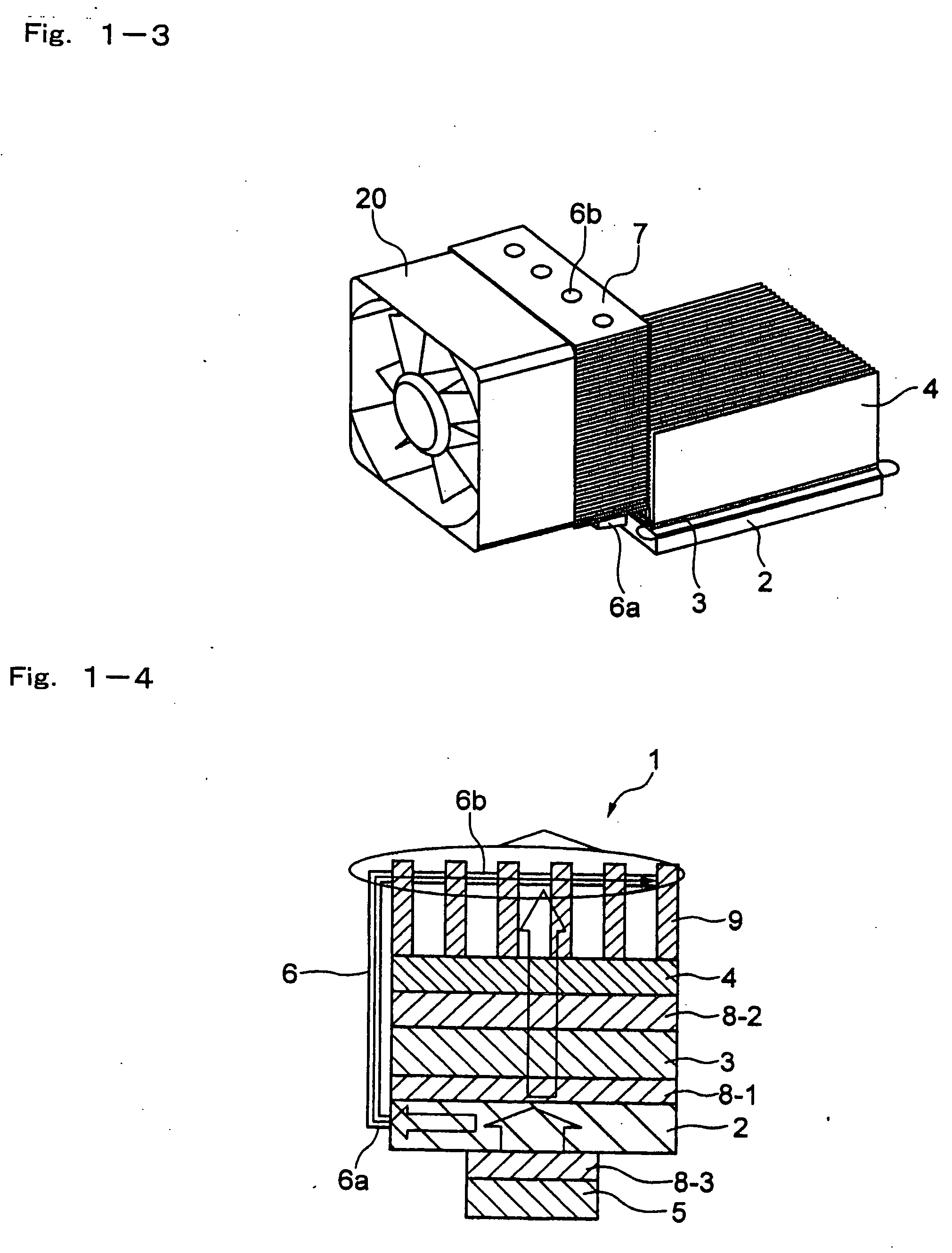
[0127] The module for cooling a heat generating element of the invention as shown in FIG. 2-2 is prepared. More specifically, a heat receiving plate formed by a material having a high thermal conductivity such as aluminum or copper is attached to a heat generating source such as a CPU mounted on a printed board. At least one prescribed recessed portion (for example, a hole) is formed in the heat receiving plate, and an end of a heat transfer device having a low thermal resistance such as a heat pipe is thermally connected to the recessed portion and fixed therein.

[0128] The other end of the heat pipe (heat transfer device) is thermally connected to a prescribed recessed portion (for example, a hole having a prescribed diameter) formed in a heat dissipating plate formed by a material having a high thermal conductivity such as aluminum or copper. The heat pipe is fixed to the above recessed portion of the hear receiving plate and the heat dissipating plate by soldering, crimping or t...

example 2

[0142] The module for cooling a heat generating element of the invention as shown in FIG. 2-4 is prepared. The module is substantially the same as the module for cooling a heat generating element as shown in FIG. 2-2 except that the heat receiving plate is arranged so as to be parallel to the heat dissipating plate. In FIG. 2-4, the first heat sink is placed at the lower side of the heat dissipating plate, however, the first heat sink may be placed at the upper side of the heat dissipating plate and the second heat sink may be place at the lower side of the heat dissipating plate.

[0143] In addition, the module for cooling a heat generating element of the invention as shown in FIG. 2-5 is prepared. More specifically, the heat receiving plate is arranged so as to be parallel to the heat dissipating plate, and furthermore, the third heat sink is attached to the heat receiving plate in addition to the first heat sink and the second heat sink as described with reference to FIG. 2-4. The...


PUM


Abstract

A module for cooling a heat generating element comprising a heat receiving plate thermally connected to at least one heat generating element; a heat transfer device one end portion of which is thermally connected to the heat receiving plate and other end portion of which is thermally connected to a heat dissipating plate; a thermoelectric cooler one face of which is thermally connected to one face of the heat dissipating plate; a first heat sink thermally connected to other face of the heat dissipating plate; and a second heat sink thermally connected to other face of said thermoelectric cooler.

Description

BACKGROUND OF THE INVENTION [0001] 1. Field of the Invention [0002] The present invention relates to a cooling device for cooling an element to be cooled having a high heat generating density such as semiconductor elements using a thermoelectric cooler (which is also referred to as TEC), for example a Peltier cooler. [0003] 2. Related Art [0004] Recently, an electronic appliance includes high power and densely integrated components such as microprocessor therein. Since the microprocessor is densely integrated and processes computing and control at high speed, a large amount of heat is generated. Various cooling systems are proposed to cool chips which are high power and densely integrated components. A heat pipe or Peltier device is represented as one of the typical cooling systems. [0005] The heat pipe comprises a round pipe shaped heat pipe and a flat shaped heat pipe. The flat heat pipe is favorably applied for cooling a component to be cooled of an electronic device such as a CP...

Claims


Application Information

Patent Timeline
IPC IPC(8): F25B21/02F25D23/12
CPCF25B21/02F25B2321/0212F28F1/32F25B2321/0252F28D15/0266F25B2321/0251
Inventor IKEDA, MASAMIKIMURA, YUICHINAKAMURA, TOSHIAKISHIMADA, MAMORU
Owner FURUKAWA ELECTRIC CO LTD
Why Eureka
Try Eureka