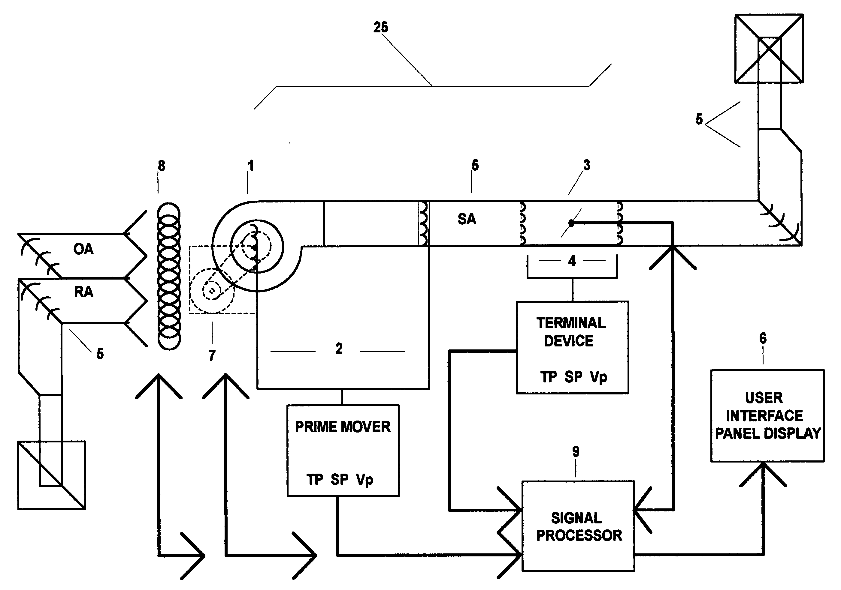
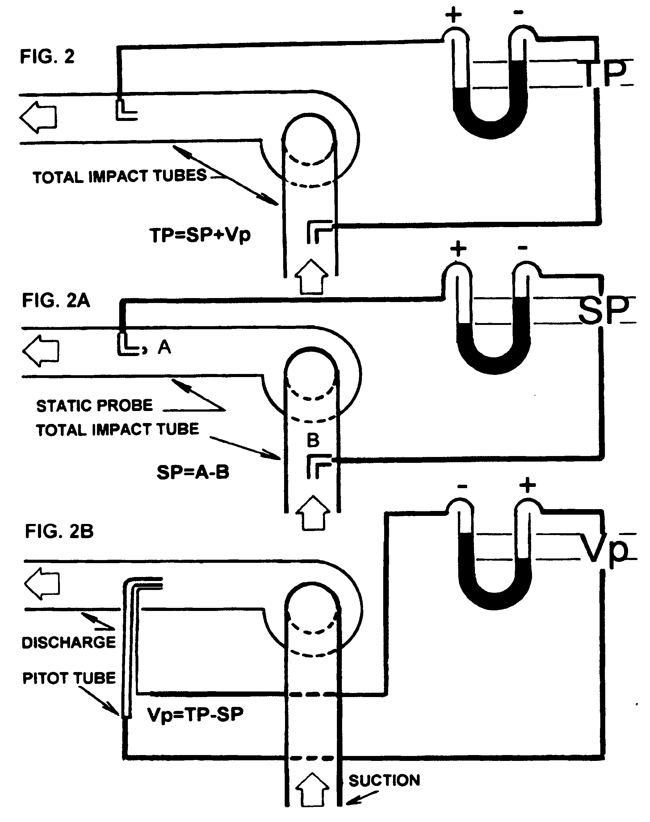
Additionally, the arrangement doesn't account for 1)
System Effect losses once the mover is fitted and packaged.
3) There is no apparent reference to
atmosphere wherein TP and SP are concerned, and establishing this may be difficult considering that the interior of building envelopes will taint the results, for the very reasons described in this specification.
This point is stressed by the known fact that field measured Static Pressure readings are considered among the least reliable data in an existing or “as-built”
system.
Furthermore, the immediate
discharge in close proximity to a blower is primarily in the form of pure, non-uniform velocity, until static regain occurs approximately 2 / 3 of the way into the
system, when there is a system.
This fact alone may contribute to misleading or misinterpreted test results as well.
These concepts still remain the source of much debate in the industry, and as a result, no consistent air-fluid
distribution control system has been adequately or consummately applied, but rather the emphasis has been more on
temperature control alone.
A common oversight in system design involves improperly
sizing or equipping a primary mover for all ranges of motion that a mixing box, face-bypass, or other
damper control system internal to the
unit housing undergoes.
The key problem arising in the above example is caused by the shift from one duct system to another, each of which has a completely different system curve assigned to it on the suction side and, thus, as a whole system.
Adding to this, this is the side where special dynamic losses, known as
System Effect losses, most
impact the performance of the primary mover in an adverse way.
Unlike most losses, these system effect losses associated with dynamic flow occur in such a way that they are not recoverable at any point in the system.
They also distort the true performance of the mover and / or system curve.
For example, adjustment to minimum conditions should never allow full
damper closure due to the necessity of maintaining minimum outside air requirements and
free flow (one way or another) that also prevents the suction side ductwork from collapsing, if conversion to 100% suction static pressure or close to it should occur.
Since the advent of single blower systems for supply and return in a single
unit housing, most ducted returns fall short of design rates before they would ever increase and, thus, seldom necessitate throttling.
This could also greatly
impact the
sizing of the primary mover for little or no reason, further complicated by the effect loss.
This and other types of controls present a similar problem to
smoke mode operation where the system curve and total
impact on the primary mover is concerned.
These automated systems also directly affect the amount of re-circulated air and cause constantly fluctuating conditions, especially in a VAV (
Variable Air Volume) system already plagued with this problem.
It is at this stage, however, that many deviations occur, mainly due to architectural and logistical changes that were never coordinated / scheduled with the rest of the trades on the building project.
One typical example might be caused by electrical conduits that were run prior to the ductwork being installed and somehow took a wrong turn around where a
light fixture was not supposed to be and, hence, blocked the path of an air duct, causing two unplanned
elbow fittings to be added where there was supposed to be straight length of run.
And this is the source of most problems on most projects, aside from poorly designed or improperly installed, leaky systems to begin with.
Due to long time vagaries associated with their proper use, however, K factors are seldom seen in catalogued equipment submittals.
Though more questionable in
discharge air readings due to taking an air measurement at the face of an RGD after the air
stream has already experienced its dynamic losses, this method is widely used by balancers to determine K factors for terminal outlets or inlets out of practical field considerations.
The
disadvantage of this distinctly different path of flow and the reason most ducted return air systems fall short of their required flow rates is that they don't have the benefit of ducted total power, and namely static pressure behind them (or rather in front of them) prior to experiencing dynamic losses at the face of their inlets.
This also distorts the actual total fan power being applied effectively, as the leaked air still returns to the mover.
These, then, are the key differences between the two terminal types and bring to light a problem in current systems with single blower return / supply air.
Also, there is the distinct
disadvantage that return air distribution cannot be precisely controlled, and this is important because it is desirable to return air exactly from zones from where it was distributed in equal measure, less any outdoor air, for optimal
recovery.
Open systems also suffer from much
dirt and outdoor air infiltration from many sources external to the conditioned zones, namely from the equipment room in close proximity to the blower and its open intake.
Partial ducting, a common problem, as with transfer ducts, does not improve the situation and cannot work effectively without direct-ducted fan power—a common oversight in system design.
Among other pitfalls of designing and maintaining an air-fluid
distribution system, the problem with catalogued K factors and any other such air-fluid flow coefficients, is that the data may be largely erroneous due to misrepresentation of actual
field conditions, the point being that the K factor is unique to a given system and must be established by field testing of that system, as opposed to tests conducted under “ideal,” static lab conditions.
Many of these infinite dimensional variations would never or could never be reproduced under lab conditions.
In fact, there are simply too many possibilities and variables within a system to warrant such constancy, as it can never be possible, especially with the unpredictable nature of “as-built” conditions caused by late shop changes to ductwork, capped extensions, turbulence or non-laminar flow, and other un-contoured paths of air-fluid flow.
Another issue with K factors involves their use in VAV systems in adjusting the sensed flow versus actual flow to a terminal
branch via a terminal
branch device (VAV box, zone
damper, valve, etc.) Currently, most leading systems are equipped with adjustment of a K factor or K “value” for given terminal
branch flow characteristics.
However simple this process may seem, it still belies the fact that the system must work harder, terminally and totally, to achieve the flow rates due to system losses producing flow factors that may be unacceptably low.
Noted discrepancies between design capacity and actual performance, however, are due to the
system characteristics of the ductwork /
piping / vessel downstream of that terminal device not readily apparent due to current control sensing limitations.
In some cases, improperly placed, connected, or malfunctioning sensors could also distort actual conditions.
The former may stem from late changes made to the terminal branch, unexpected losses due to obstructions, acute bends or turns, changes to
sizing of the terminal device for its range and capacity versus any revised terminal branch
system requirements, etc.
Additionally, an effect caused by downstream throttling of terminal or
takeoff branches contributes to adverse effects, as this may confuse current flow sensors, which, contrary to popular belief are more precise in taking measurements in closer proximity to the terminal / in-line device or flow
station at which they are situated.
The key problem, however, lies in the issue of making best use of this conversion.
It does, however, exist dormant within the system so long as mover power is applied.
Otherwise, it becomes leakage at one or more points in the system.
One adverse result of this is that more input power must be applied to achieve the same flow rates at terminal outlets.
Among previously mentioned problems, current DDC (Direct Digital Controls) also suffer from quite severe limitations imposed by their very linear nature, namely the linear nature of the micro controllers they are comprised of, because mechanical, thermal, and fluid dynamic relationships are anything but linear.
However, where actual field-testing is concerned, these conditions always vary and stray quite abroad, especially at low and high ends of the spectrum when dealing with a lab-tested mover in the constantly changing framework of a real, “as-built” system.
This point also conflicts with current use of temperature sensor-oriented controls, which are not governed by the affinity laws or even thermal dynamics.
The key problem remains, however, that they go little or no further in obeying the laws of thermal dynamics or fluid
mechanics, or in making use of them for efficiency or effectiveness.
The crux of the problem lies in correct sensor interpretation and
signal utilization.
Any other method, therefore, must be assumed to be grossly limited, if not wholly incorrect, particularly if based on principles of temperature zone sensing and direct damper control alone with localized, unilateral feedback.


