Shower plate for plasma processing apparatus and plasma processing apparatus

a plasma processing apparatus and plasma technology, applied in the field of shower plates, can solve the problems of reducing the effective diameter of the shower plate b>22/b>, increasing production costs, and generating contamination, so as to improve production efficiency, facilitate manufacturing, and prevent contamination of the substrate to be treated

Inactive Publication Date: 2005-11-24
SHIN ETSU CHEM IND CO LTD
View PDF3 Cites 386 Cited by
  • Summary
  • Abstract
  • Description
  • Claims
  • Application Information

AI Technical Summary

Benefits of technology

[0015] The present invention has been accomplished to solve the above-mentioned problems, and a main object of the present invention is to provide a shower plate for a plasma processing apparatus that an effective diameter is large enough, contamination of the substrate to be treated can be prevented, it is easy to manufacture, and it is easy to fix to the supporting member.
[0021] The shower plate having such a structure is easy to manufacture. Furthermore, the shower plate is easy to put on and taken off by just turning it with respect to the supporting member without auxiliary parts like the socket, so that it is excellent in workability. In addition, a cover ring is not necessary and the effective diameter is large enough. And because the fastening member like screws and so on are not exposed, contamination of a substrate to be treated like a wafer and so on can be prevented effectively.
[0023] As described above, when the width of the fitting portion is formed larger than that of the groove portion by the range of 1-20 mm, it is very easy to manufacture, and holding power to fix the shower plate is obtained enough, so that the shower plate is fixed securely.
[0025] If the shower plate has the above size, its material is easily available, and the holes are also easily formed. Furthermore, because a silicon wafer being a typical substrate to be treated has mainly a diameter in the range of 200-300 mm, the whole of a wafer can be processed uniformly by using the shower plate having the above size.
[0027] As described above, if the plasma processing apparatus is provided with the shower plate according to the present invention, a substrate to be treated like a silicon wafer and so on can be processed without contamination because the fastening member like screw and so on is not exposed. In addition, there's no need for auxiliary parts like cover ring and so on, so that it leads to cost reduction.
[0028] As described above, the shower plate according to the present invention can be easily put on and taken off by turning with respect to the supporting member, so that workability is extremely excellent. In addition, there is no need for auxiliary parts like cover ring, socket and so on, so that it leads to cost reduction. And also, the shower plate can be fixed to the supporting member without exposure of the fastening member. Accordingly, contamination of a substrate to be treated can be prevented effectively.

Problems solved by technology

However, even if the shower plate made of silicon is used, said screws for fixing the shower plate are exposed on the side facing the wafer, which becomes a source of generation of the contamination.
Furthermore, because the gas feeding holes cannot function in the outside region covered by the cover ring 29, there is a drawback that the effective diameter of the shower plate 22 substantially becomes smaller.
However, structures of the sockets and the holes for inserting the sockets are complicated, and therefore production cost increases.
It is difficult to work with checking the correspondence.
Thus there is a problem that the work to fix the shower plate to the supporting member is complicated.

Method used


Image

  • Shower plate for plasma processing apparatus and plasma processing apparatus
  • Shower plate for plasma processing apparatus and plasma processing apparatus
  • Shower plate for plasma processing apparatus and plasma processing apparatus

Examples


example

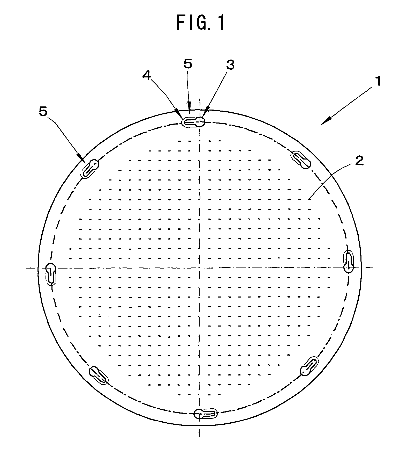
[0058] A plate having a diameter of 350 mm and a thickness of 10 mm was prepared from a base material of silicon single crystal ingot.

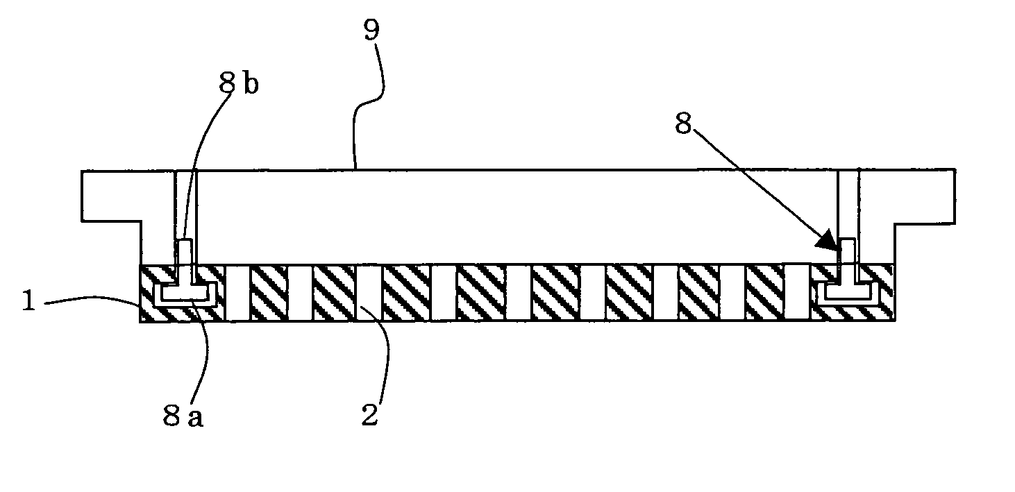
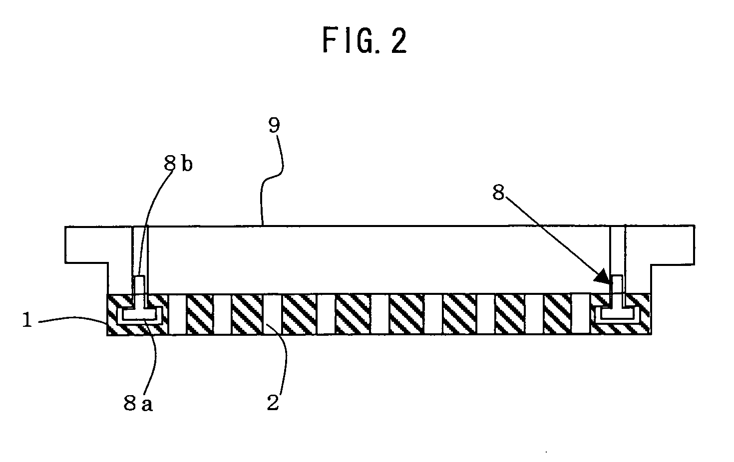
[0059] After through-holes that function as gas feeding holes were formed in the plate along the direction of the thickness, a hole for inserting the fastening member and a hole for fitting it were formed to be one unit on the side facing the supporting member, at 8 places along a concentric circle in the outside region of the gas feeding holes. Here, each hole for insertion was formed as a countersink having a diameter of 10 mm and a depth of 8 mm. On the other hand, each hole for fitting was formed to extend counterclockwise with inclining by 5° along a concentric circle on which the holes for insertion are formed, at the same time a step was formed in the direction of depth so that the hole for fitting may comprise the fitting portion having a diameter of 10 mm and a maximum depth of 8 mm, and the groove portion (aperture) having a width of 5 mm a...


PUM

PropertyMeasurementUnit
widthaaaaaaaaaa
thicknessaaaaaaaaaa
thicknessaaaaaaaaaa

Abstract

There is disclosed a shower plate 1, wherein the shower plate has a plurality of holes 3 for inserting the head of the fastening member and holes 4 for fitting the head are formed integrally along a concentric circle in the outside region of the gas feeding holes 2 on a side facing the supporting member, each hole for fitting extending in one direction of the concentric circle from each hole for insertion, each hole for fitting has a groove portion 4b through which the shank of the fastening member is to pass and a fitting portion 4a which is wider than the groove portion and in which the head of the fastening member is to be fitted, and the head of the fastening member fixed in the supporting member is inserted into the hole for insertion of the shower plate and the shower plate is turned so that the head of the fastening member is fitted in the fitting portion, and thereby the shower plate is supported by the supporting member without exposure of the fastening member. There can be provided a shower plate for a plasma processing apparatus, wherein effective diameter is large enough, contamination of a substrate to be treated can be prevented, it is easy to manufacture, and it is easy to fix to a supporting member.

Description

BACKGROUND OF THE INVENTION [0001] 1. Field of the Invention [0002] The present invention relates to a shower plate for a plasma processing apparatus and a plasma processing apparatus used for dry plasma etching of a substrate such as a semiconductor wafer. [0003] 2. Description of the Related Art [0004] As one of apparatuses for fabricating a semiconductor device, a parallel plate plasma processing apparatus represented by a plasma dry etching apparatus is conventionally used. As shown in FIG. 4, for example, in a chamber 26 of plasma processing apparatus 20, an upper electrode unit 24 is disposed opposite a lower electrode 23. [0005] The upper electrode unit 24 is mainly composed of a supporting member 21 and a shower plate 22 which are made of aluminum and the like. Many through-holes (gas feeding holes) 25 for feeding reaction gas are formed in the shower plate 22 and holes (not shown) for fixing the shower plate 22 to the supporting member 21 are formed in the outside region of...

Claims


Application Information

Patent Timeline
Patent Type & Authority Applications(United States)
IPC IPC(8): H05H1/46B05B1/18B05B3/04C23C8/36H01J37/32H01L21/3065
CPCB05B1/185H01L21/3065H01J37/3244C23C8/36
Inventor GOTO, KEIICHIKAWAI, MAKOTOSATOH, KENJI
Owner SHIN ETSU CHEM IND CO LTD
Why Eureka
Try Eureka