Power source device

a power source and power supply technology, applied in the field of power supply units, to achieve the effect of increasing internal resistan

Inactive Publication Date: 2005-12-08
SONY CORP
View PDF1 Cites 53 Cited by
  • Summary
  • Abstract
  • Description
  • Claims
  • Application Information

AI Technical Summary

Benefits of technology

[0033] Since the outputs of the plurality of cells are output so as to match the parallel connection, a cell outputting a low curren...

Problems solved by technology

Moreover, since the output voltages, which are adjusted so as to be the same, are output to the common termi...

Method used


Image

  • Power source device
  • Power source device
  • Power source device

Examples


first embodiment

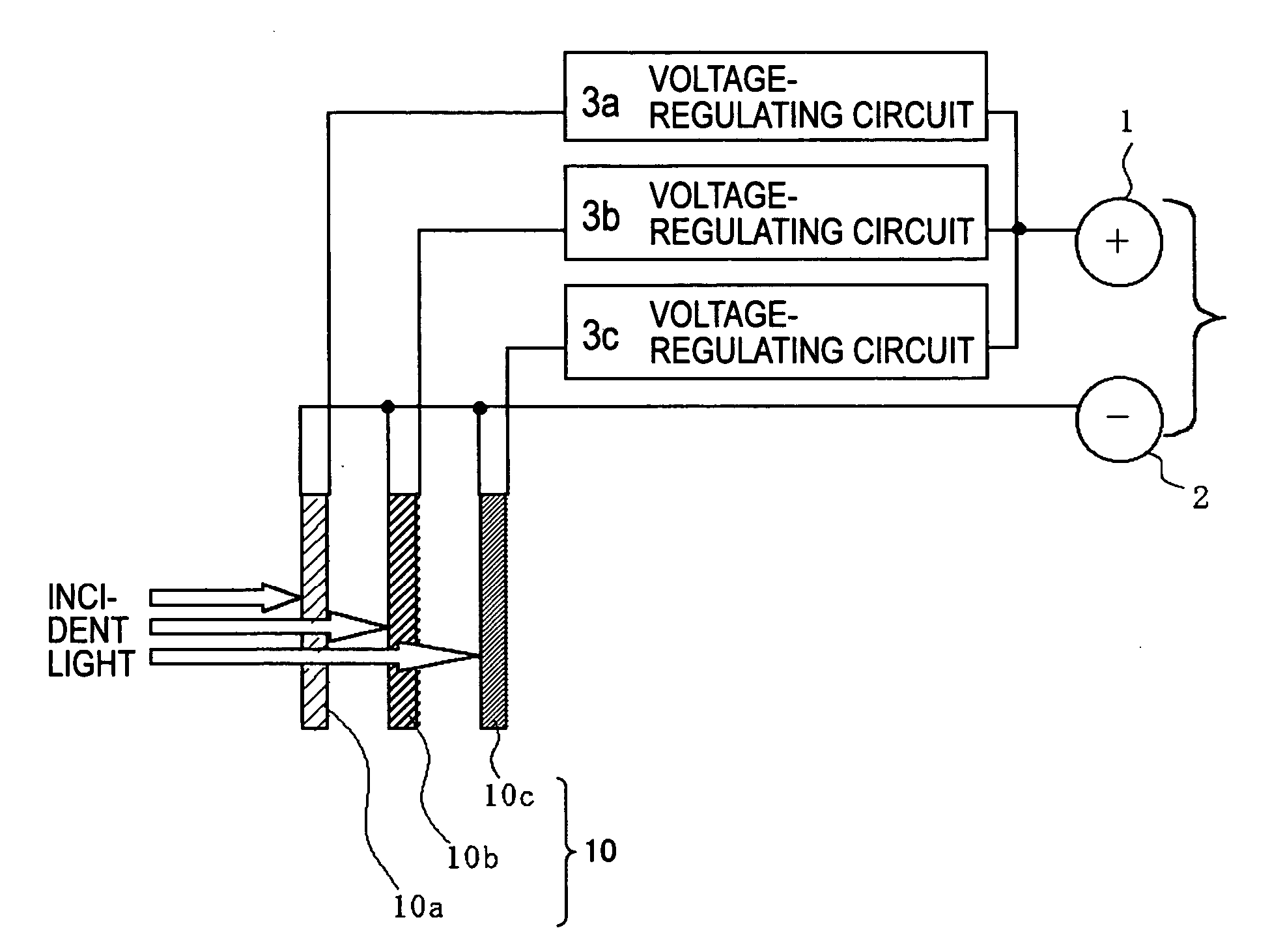
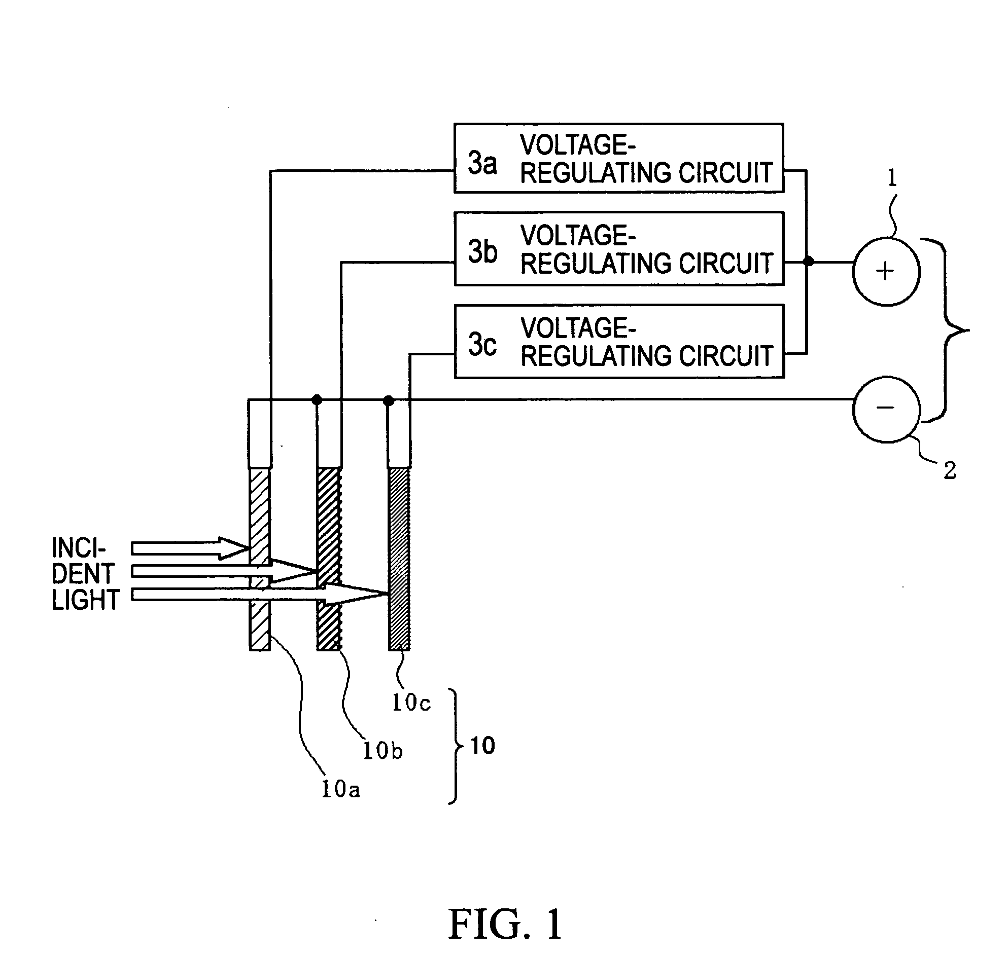
[0050]FIG. 1 is a schematic block diagram illustrating a power supply unit in which outputs of tandem photoelectric transducers 10a to 10c in a tandem wet solar cell 10 are connected in parallel to common output terminals 1 and 2 through voltage-regulating circuits 3a to 3c.

[0051]FIG. 10A is a schematic sectional view of the tandem wet solar cell 10. In the tandem wet solar cell 10, from the position closest to the incident light, the tandem photoelectric transducers 10a, 10b, and 10c are respectively retained in a first layer, a second layer, and a third layer, these layers being formed by a transparent substrate 11, two spacers 20, and another substrate 19.

[0052] The spacers 20 are composed of a transparent material and have a shape allowing light to pass through. The spacers 20 may be, for example, transparent glass plates or transparent plastic plates composed of, e.g., polyethylene terephthalate or polycarbonate. Since the substrate 19 is not required to transmit light, a non...

second embodiment

[0073]FIG. 3 is a schematic block diagram illustrating a power supply unit that stores energies generated by tandem photoelectric transducers 10a, 10b, and 10c, respectively, of a tandem wet solar cell 10 in capacitors 4a, 4b, and 4c as electric charge. The power supply unit then outputs the energies stored in the capacitors by time-sharing as currents at the same voltage across common output terminals 1 and 2 through a voltage-regulating circuit 3d that can connect to the capacitors.

[0074] This output technique using switched capacitors is a modification of the output technique in the first embodiment. Since outputs of the tandem photoelectric transducers 10a to 10c are not simultaneously connected to the common output terminal 1 after the voltages are adjusted, these outputs are not connected to each other in parallel in the strict sense. However, this output technique matches the parallel connection in that all the tandem photoelectric transducers 10a to 10c are substantially co...

third embodiment

[0079]FIG. 4 is a schematic block diagram illustrating a power supply unit according to a third embodiment. The power supply unit includes tandem photoelectric transducers 10a to 10c in respective photoelectric layers, each transducer including many small cells having the same size. The power supply unit produces the same output voltages in all the layers only by setting connections among the small cells in each layer and outputs these voltages in parallel across the common output terminals 1 and 2. This embodiment does not need a voltage-regulating circuit such as a voltage step-up / step-down circuit, unlike the first and second embodiments.

[0080] Double connecting lines in FIG. 4 indicate that the small cells are connected in a matrix by both the series and the parallel connections. In practice, a number of rows, each including a predetermined number of small cells connected in series, are connected to each other in parallel. Hereinafter, the small cells connected in a matrix are ...


PUM


Abstract

A power supply unit composed so that outputs from a plurality of cells having different output characteristics are output from common terminals and so that a decrease in energy efficiency caused by connecting the cells is suppressed to the utmost is provided. After outputs of a plurality of cells 10a to 10c having different output voltages and output currents are adjusted to have the same output voltage value, the outputs are output to terminals 4 and 5 so as to match the parallel connection. Since the outputs of the cells are output in parallel, a cell outputting a low current does not restrict the output currents in the overall power supply unit, unlike the series connection. Moreover, since the outputs, which are adjusted to have the same voltage, are connected, problems such as flowback do not occur. In the case where the present invention is applied to a tandem solar cell, a light-absorbing wavelength characteristic can be assigned to each tandem photoelectric transducer so that solar light is utilized at the maximum efficiency, and the photoelectric energy conversion efficiency does not decrease even when the wavelength distribution of solar light deviates from the standard one.

Description

TECHNICAL FIELD [0001] The present invention relates to power supply units including cells, for example, solar cells (photoelectric transducers) and chemical cells. BACKGROUND ART [0002] Solar cells utilizing solar light have been regarded as energy sources to replace fossil fuels. A variety of studies have been done. A solar cell is a type of photoelectric transducer for converting light energy into electrical energy. [0003] In the current most popular solar cells using the pn junction of semiconductors or a heterojunction of dissimilar materials, among photons entering, for example, a pn junction, those photons that have energy larger than band-gap energy of a semiconductor are absorbed. Thereby, electrons in the valence band are excited into the conduction band, and holes are simultaneously generated in the valence band. Electron-hole pairs are generated in a semiconductor in this way, and an internal electric field created in the pn junction causes the electrons to move toward t...

Claims


Application Information

Patent Timeline
IPC IPC(8): H01L31/04H01G9/20H01L25/00H01L31/00H01M14/00H01M16/00H02J7/00H02J7/35
CPCH01G9/2031H01G9/2063Y02E10/542H01G9/2072H02J7/35H01G9/2068H02S10/00
Inventor ENOMOTO, MASAHIHONDA, TOSHIO
Owner SONY CORP
Why Eureka
Try Eureka