Filter to improve dispersion tolerance for optical transmission

a filter and optical transmission technology, applied in electromagnetic transmitters, electrical equipment, electromagnetic transmission, etc., can solve the problems of increasing dispersion penalty and giving penalty, and achieve the effect of reducing phase differen

Inactive Publication Date: 2005-12-08
NORTEL NETWORKS LTD
View PDF11 Cites 113 Cited by
  • Summary
  • Abstract
  • Description
  • Claims
  • Application Information

AI Technical Summary

Benefits of technology

[0009] It is an object of the present invention to provide improved apparatus and methods. According to a first aspect of the present invention, there is provided a system having a transmitter for transmitting an optical signal along a transmission path, the transmitter having a directly modulated laser for modulating data directly on the optical signal, the system having a receiver for receiving the transmitted optical signals to recover the data, and a narrow band optical filter having a band center frequency offset from a central optical frequency of the optical signal, to reduce a phase difference between FM and AM of the modulated optical signal, the filter having a bandwidth sufficiently narrow to substantially remove damped oscillatory transients in frequency that fall outside the spectrum of adiabatic frequency chirp resulting from the modulation, combined with Fourier broadening caused by the data.

Problems solved by technology

The former can produce a dispersion penalty which increases at longer distances.
The latter gives a penalty particularly at shorter distances, and occurs even for ASK (amplitude shift keying), since directly modulated lasers usually produce some unwanted adiabatic frequency chirp.

Method used


Image

  • Filter to improve dispersion tolerance for optical transmission
  • Filter to improve dispersion tolerance for optical transmission
  • Filter to improve dispersion tolerance for optical transmission

Examples


Embodiment Construction

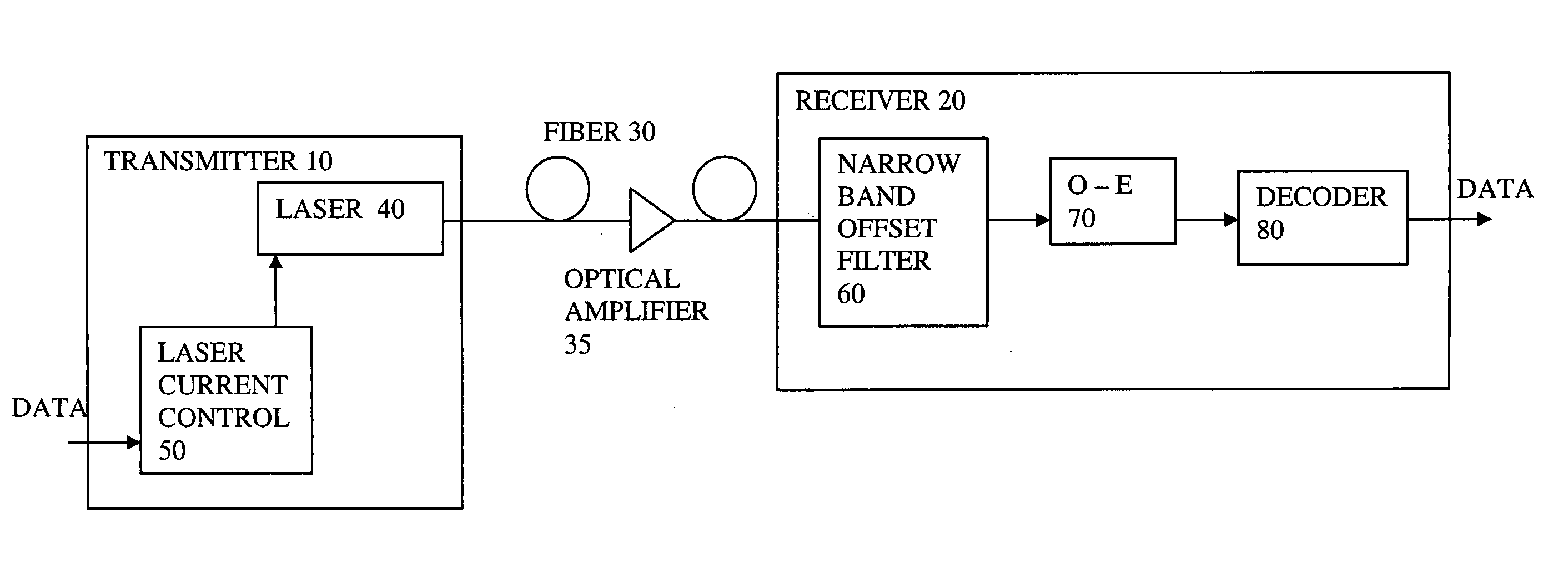
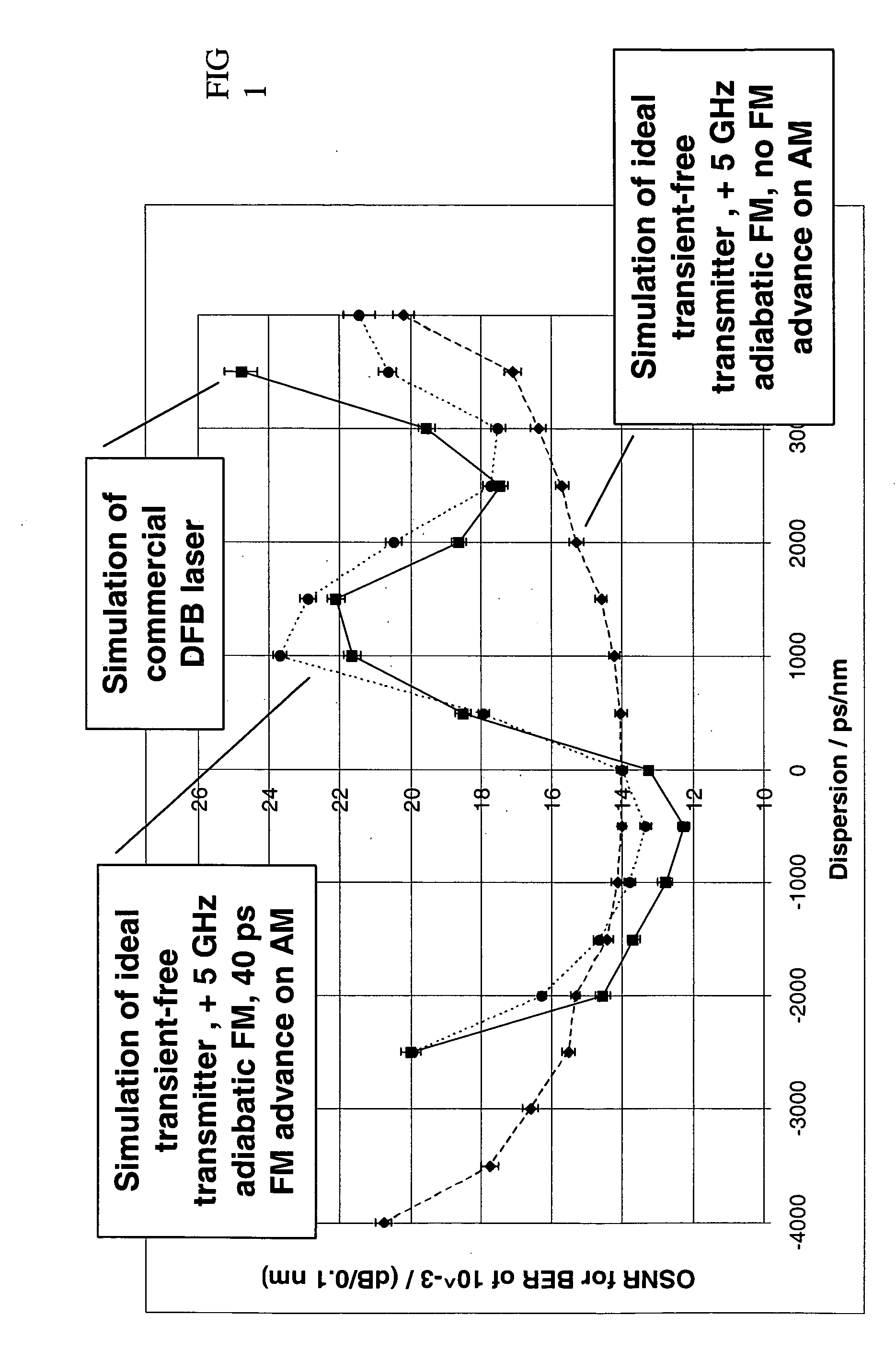
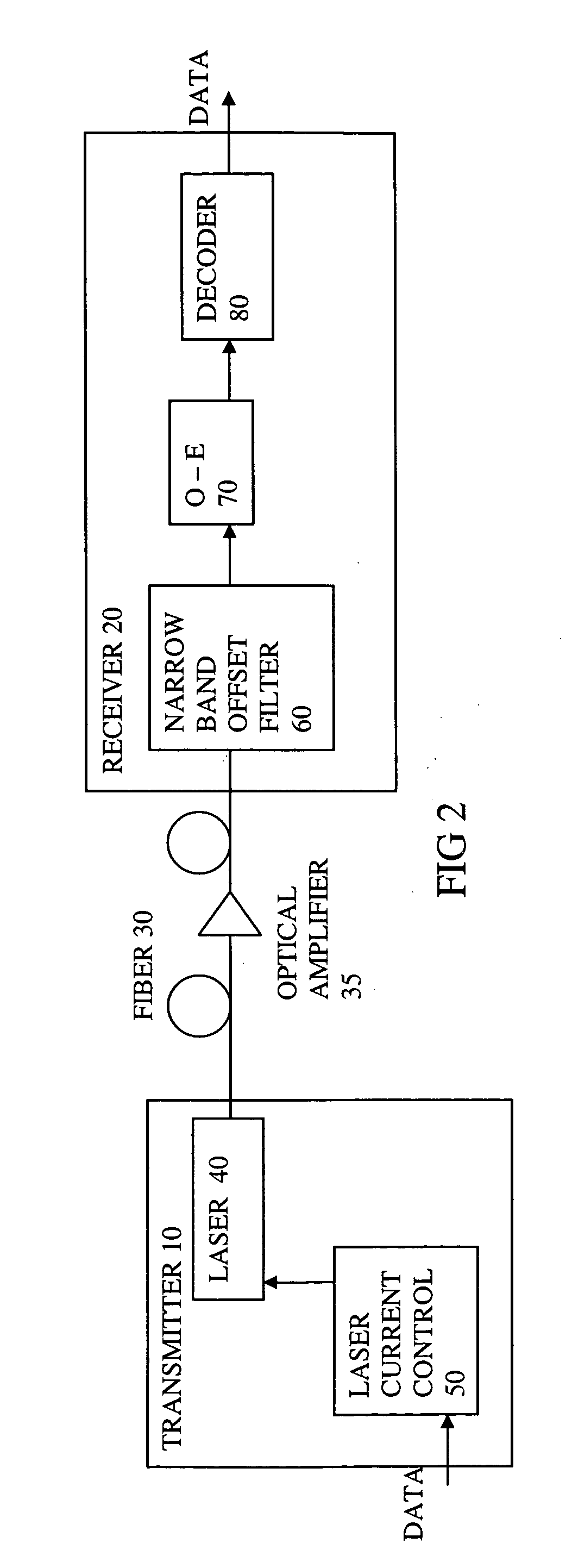
[0057] Directly modulated DFB lasers exhibit a damped oscillatory transient response in frequency and power when switched between ‘0’ and ‘1’ levels. They emit at different frequency in steady-state ‘0’ and ‘1’ levels, referred to as adiabatic frequency chirp. Notably adiabatic frequency chirp, combined with the delayed response of AM compared with FM, has been identified as the cause of a peak in the OSNR penalty for small positive dispersions (˜1000 ps / nm). The narrowband filter should reduce the FM timing advance on AM to approximately 4000 ps / nm). FIG. 1 shows schematically how the optical signal to noise ratio (OSNR) for a bit error rate (BER) of 10−3 varies with the dispersion. The horizontal axis can also represent distance along a dispersive fiber, and so the plotted curves show the tolerance of the system to optical noise at different dispersions or reaches at a BER of 10−3. A system with add-drop nodes will, for example, contain multiple optical amplifiers to compensate fo...


PUM


Abstract

An optical transmission system has a directly modulated laser for modulating data directly on an optical signal, and a narrow band optical filter having a band center frequency offset from a central optical frequency of the optical signal, to reduce the phase difference between FM and AM of the modulated optical signal, the filter having a bandwidth sufficiently narrow to substantially remove frequencies outside a spectrum of adiabatic frequency chirp resulting from the modulation, combined with Fourier broadening caused by the data modulation. This is a cost effective way of improving the dispersion tolerance to give greatly improved system reach and to make it practical to use directly modulated lasers with existing NDSF. The narrow band filter can be located at the transmitter or the receiver, and can have a center frequency locked to a feature in the frequency spectrum of the laser.

Description

FIELD OF THE INVENTION [0001] This invention relates to systems for optical transmission, to receivers or transmitters for such systems, and to methods of offering a transmission service over such apparatus. BACKGROUND TO THE INVENTION [0002] It is known to transmit optical signals in long-haul dense wavelength division multiplexed (DWDM) networks, using directly modulated DFB (distributed feed back) lasers. The principal advantage of such lasers is their low-cost and straightforward implementation. However, system performance in terms of reach, can be limited by frequency chirping, which results in pulse broadening in a dispersive single-mode fiber. Another limiting effect is wavelength drift due to aging of the laser. [0003] It is known from IEEE PHOTONICS TECHNOLOGY LETTERS, VOL. 13, NO. 1, JANUARY 2001 pages 58-60 that temporal reshaping of the optical pulses by filtering the output of a directly modulated transmitter can decrease the dispersion penalty. The filter can be a Fabr...

Claims


Application Information

Patent Timeline
Patent Type & Authority Applications(United States)
IPC IPC(8): H04B10/04H04B10/18
CPCH04B10/25133
Inventor WHITEAWAY, JAMESHEATH, RICHARDPETTITT, GARYBRUCE, PAUL
Owner NORTEL NETWORKS LTD
Why Eureka
Try Eureka