Method for manufacturing membrane electrode assembly of fuel cell by printing processes

US20050276913A1Inactive Publication Date: 2005-12-15INST NUCLEAR ENERGY RES ROCAEC

Image

  • Method for manufacturing membrane electrode assembly of fuel cell by printing processes
  • Method for manufacturing membrane electrode assembly of fuel cell by printing processes
  • Method for manufacturing membrane electrode assembly of fuel cell by printing processes

Examples


Embodiment Construction

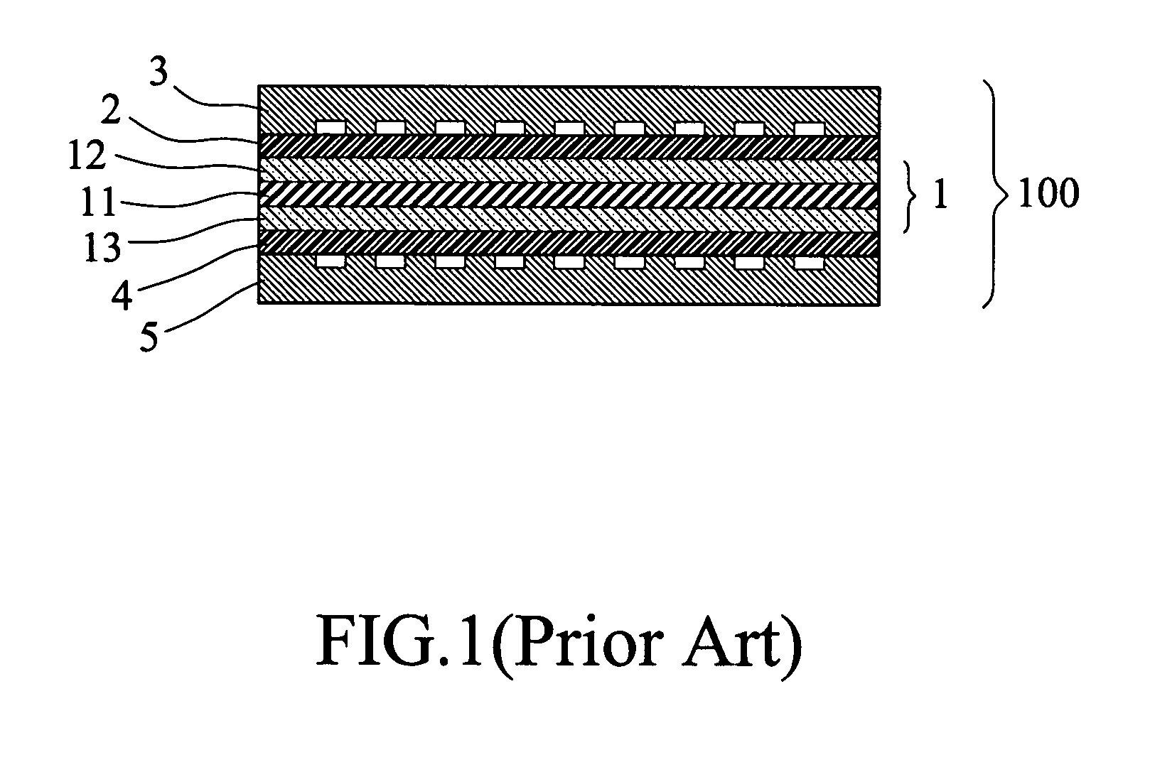
[0027] The present invention discloses a method for manufacturing a membrane electrode assembly (MEA) of a fuel cell by printing. An MEA is comprised of an ion exchange membrane having opposite surfaces on which anode catalyst and cathode catalyst are coated respectively. In the method in accordance with the present invention, the ion exchange membrane is cleaned first in a cleaning process and anode catalyst solution and cathode catalyst solution are prepared in a catalyst solution preparation process before a printing operation for the formation of the MEA is performed. These processes will be described in details hereinafter.

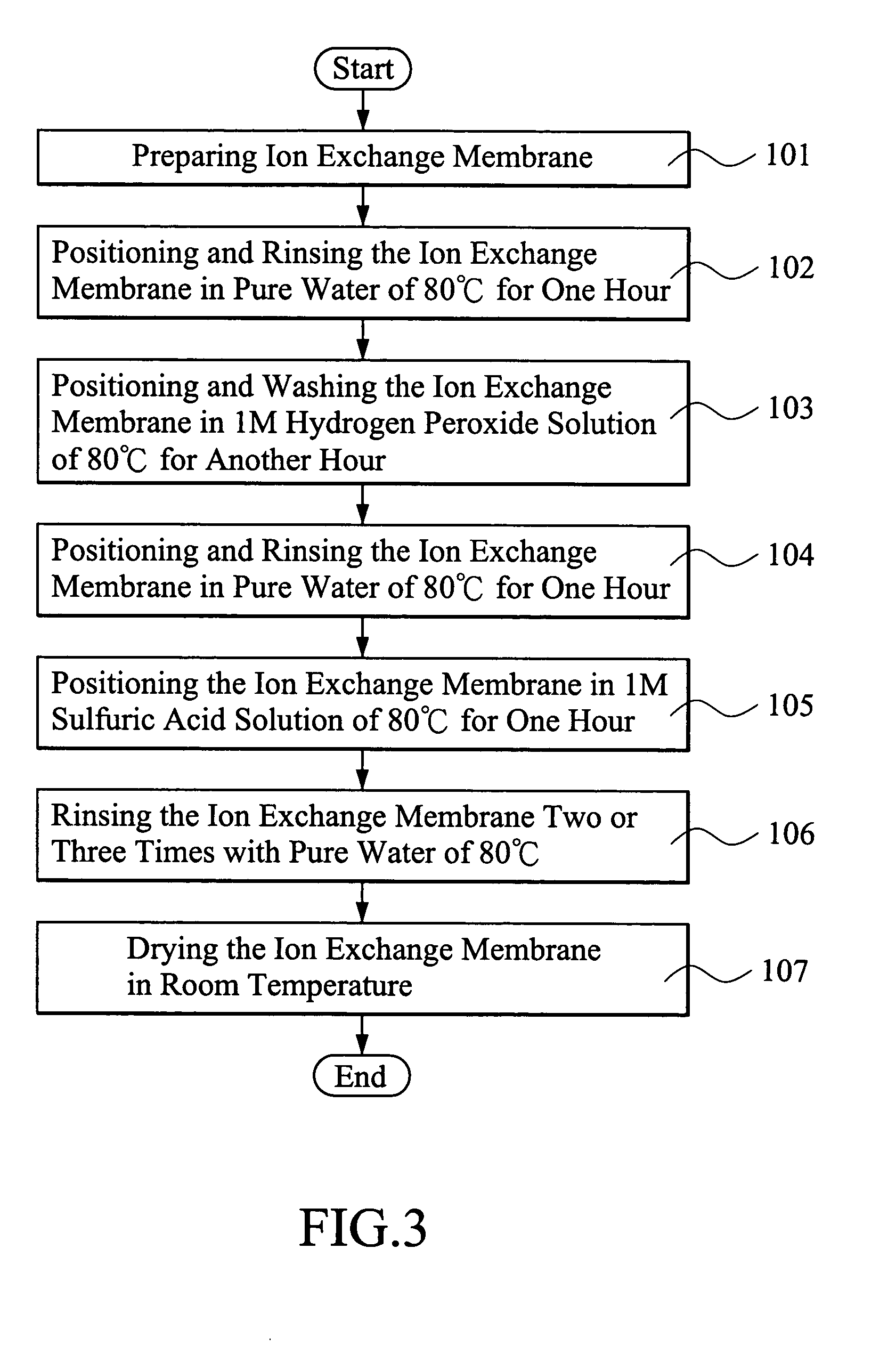
[0028]FIG. 3 shows the ion exchange membrane rinsing process. An ion exchange membrane is prepared first (step 101). A suitable example for the ion exchange membrane is Nafion® of Du Pont Corporation. A preferred example of the ion exchange membrane is Nafion 117 having a thickness of 175 μm, which is considered thick enough to block transmission / penetration...


PUM

PropertyMeasurementUnit
Temperatureaaaaaaaaaa

Abstract

A method for manufacturing membrane electrode assembly of fuel cell includes positioning an ion exchange membrane that is cleaned and trimmed to a predetermined size in advance to a base plate, mounting the base plate to a printing platform, attaching a printing plate to the platform, coating a catalyst solution on the printing plate with a scraper, printing the catalyst solution onto the ion exchange membrane with the scraper, heating the ion exchange with a heating board to a temperature of 70-80° C., and waiting for the ion exchange membrane to return flat to complete the coating of the catalyst solution on the ion exchange membrane. The printing and heating steps are repeated for both anode and cathode of the ion exchange membrane. The ion exchange membrane is further subject to hot pressing and then a piece of carbon cloth is positioned on the catalyst coating to serve as a diffusion layer. This completes the manufacturing of the membrane electrode assembly.

Description

BACKGROUND OF THE INVENTION [0001] 1. Field of the Invention [0002] The present invention relates generally to a manufacturing method for membrane electrode assembly of fuel cells, and in particular to a method for formation of membrane electrode assembly by printing processes so as to eliminate swelling and cracking of the membrane electrode assembly. [0003] 2. The Related Art [0004] Fuel cells are an electro-chemical device that makes use of electrochemical reaction between a fuel containing hydrogen and an oxidizer, such as oxygen contained in the surrounding air, to generate electrical power. The fuel cells are advantageous in low contamination, high efficiency and high power density. Thus, developments and researches are intensively devoted to the fuel cell field for exploitation of the utilization thereof. [0005] A typical fuel cell stack is made up of a structure comprising several layers of which an intermediate layer is constituted by an ion exchange membrane that allow for...

Claims


Application Information

Patent Timeline
15 Dec 2005
Publication
US20050276913A1
IPC
B05D5/12; H01M4/86; H01M4/88; H01M4/90; H01M4/92; H01M8/10
CPC
B41M1/12; B41M1/26; H01M4/881; Y02E60/50; H01M4/8835; H01M4/8882; H01M4/926
Inventors
CHEN, CHARN-YING; YANG, PENG