High-speed vision sensor

a high-speed, sensor technology, applied in the field of high-speed vision sensors, can solve the problems of limited image processing speed in modern vision systems, inability to take full advantage of robot performance, and only operating at low speeds that match this image processing speed, so as to achieve high-speed data transfer operation, facilitate data transfer speed, and processing can be performed efficiently

Inactive Publication Date: 2005-12-22
HAMAMATSU PHOTONICS KK
View PDF15 Cites 37 Cited by
  • Summary
  • Abstract
  • Description
  • Claims
  • Application Information

AI Technical Summary

Benefits of technology

[0008] In view of the foregoing, it is an object of the present invention to provide a multi-pixel high-speed vision sensor which has a simple circuit construction and which is capable of performing basic image processing at a high speed.
[0010] According to the present invention, the plurality of processing elements are provided in one to one correspondence with the plurality of photodetectors. It is therefore possible to perform high-speed image processing operation by parallel processing. Additionally, the analog-to-digital converter is provided to each row. Accordingly, the total number of transmission paths can be reduced.
[0011] Additionally, there are provided, with respect to each processing element, a data bus which is dedicated to transferring data in a row direction, and another data bus which is dedicated to transferring data in a column direction. It is therefore possible to perform various image processing calculations. It is possible to attain a flexible processing performance while maintaining the architecture suitable for integration of the semiconductor elements.
[0016] It is preferable that the high-speed vision sensor may further comprise data buffers which are provided in correspondence with the column-direction data-transfer bus and the row-direction data-transfer bus, respectively. By providing the high-speed vision sensor with the data buffers, it is possible to perform high speed data transfer operation even when data transfer speed between the control circuit and the data transfer buses is low. By integrating together the parallel processing system, the data transfer buses, and the data buffers, it is possible to relatively easily enhance the data transfer speed, at which data is transferred between the processing elements and the buffers.
[0017] It is preferable that the parallel processing system further includes a shift register array, the shift register array having a plurality of shift registers which are disposed in one-to-one correspondence with the plurality of analog-to-digital converters and in one-to-one correspondence with the plurality of rows of processing elements, each shift register successively transferring digital signals, which are outputted from the corresponding analog-to-digital converter and which are equivalent to signals outputted from the photodetectors in a corresponding photodetector row, to predetermined processing elements in the corresponding row. The shift registers are used as being dedicated to transferring data to the processing elements. Accordingly, calculation processing can be performed even during the transfer process. Processing can be performed efficiently by reducing the wait time for both of the transfer process and the calculation process, thereby reducing the overall processing time. It is possible to achieve a pipeline operation, and to perform a high-speed image processing, and particularly real-time processing.

Problems solved by technology

However, because the image processing speed in modern vision systems is limited by the video frame rate, the robot can only operate at low speeds that match this image processing speed.
It is impossible to take full advantage of the robot's performance.
However, the devices have almost no real-time capability, and are not suitable for controlling robots or similar real-time applications.
The type of image processing they can perform is limited to special applications.
It requires a lot of time to transfer the positional information to the processing elements.

Method used


Image

  • High-speed vision sensor
  • High-speed vision sensor
  • High-speed vision sensor

Examples


example 1

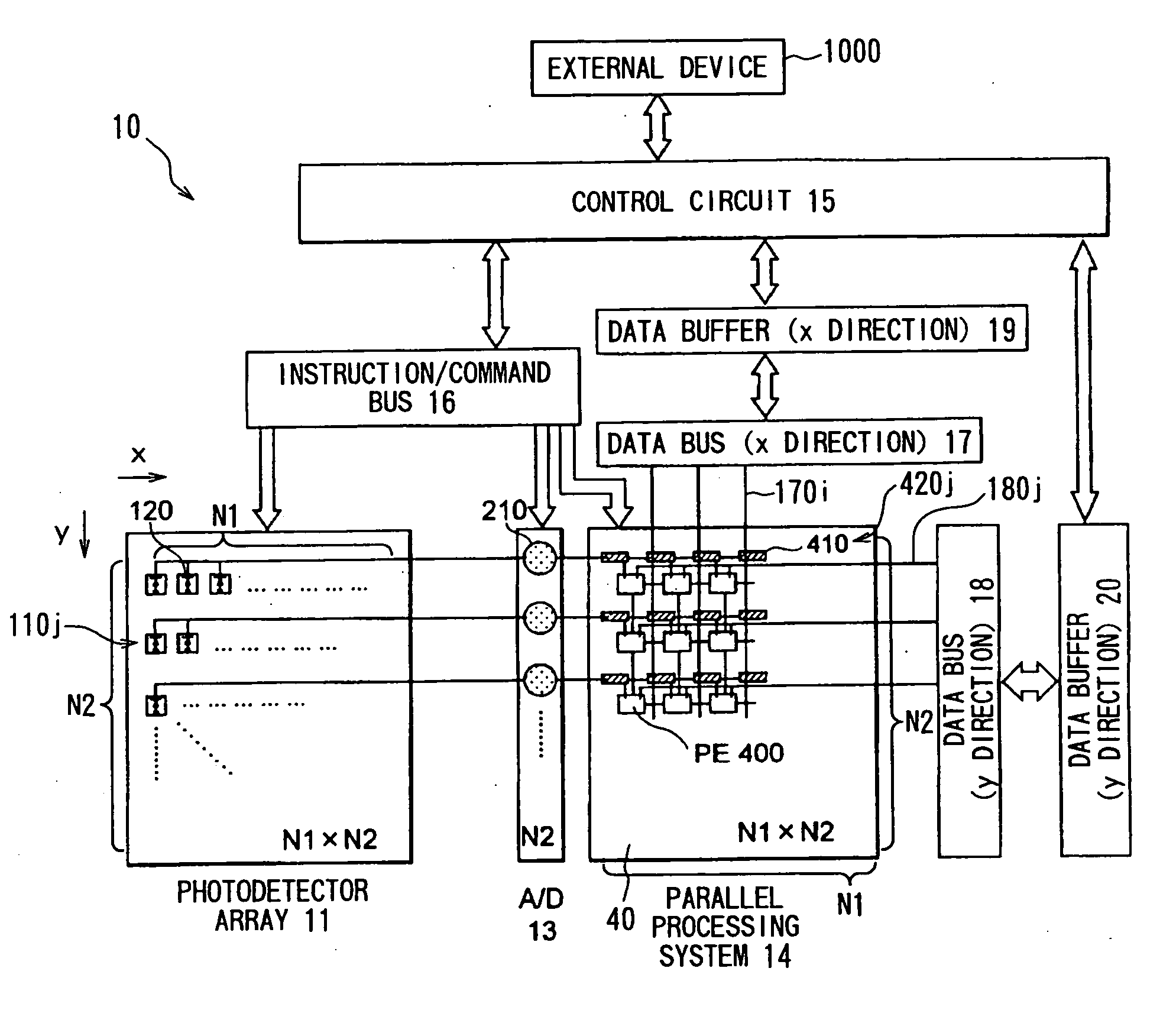
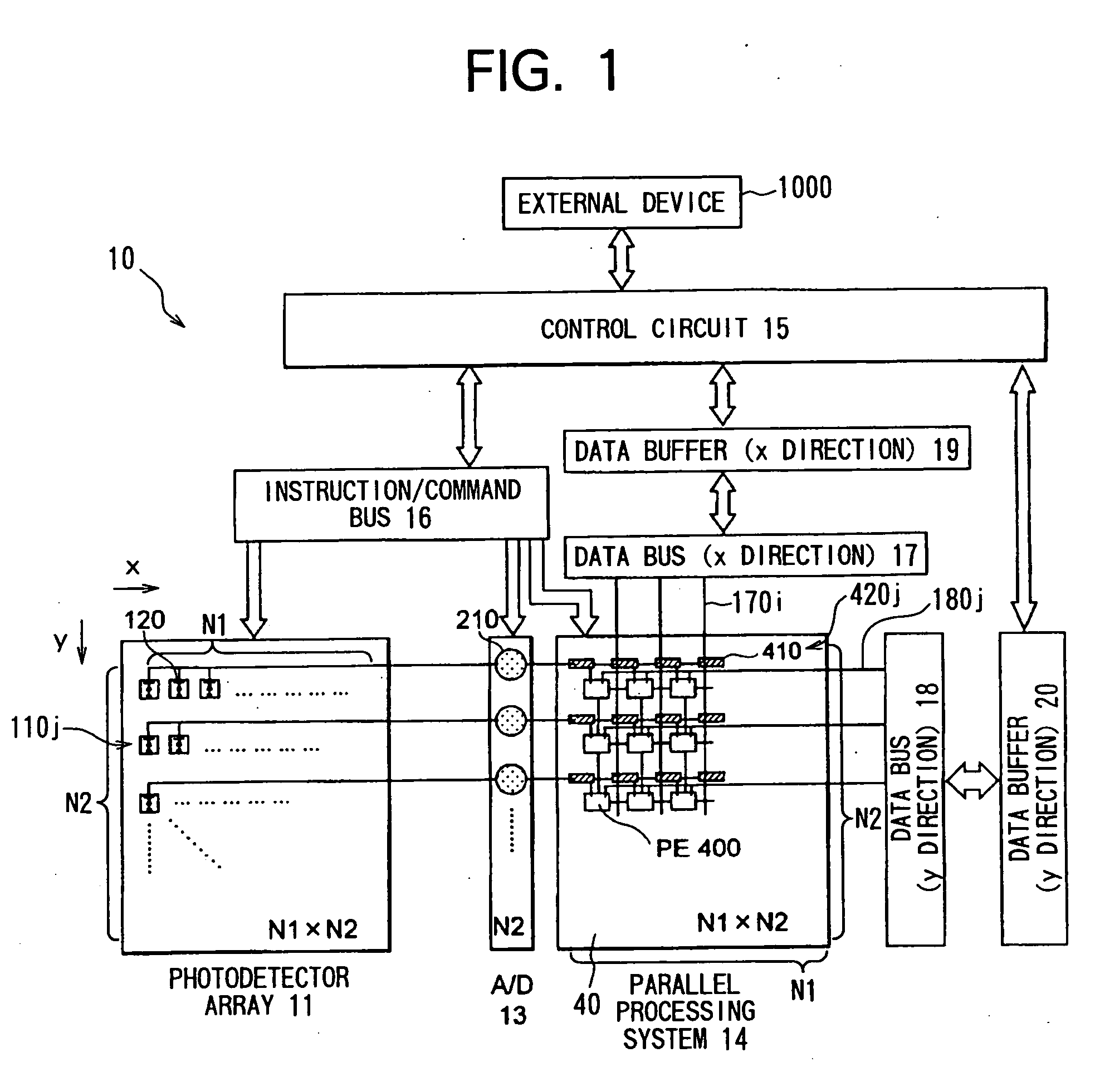
[0102] According to the present embodiment, calculation data and calculation-control data can be supplied to each processing element within a short period of time via the x-direction data bus 17 and the y-direction data bus 18 from outside. Accordingly, calculation can be attained at a high speed even when each processing element 400 performs in S110 a type of calculation that requires additional data other than image information. For example, in order to calculate the center of gravity of the input image during the image processing step (S110), the processing elements require positional information data. Accordingly, positional data is supplied from outside to the processing elements, which in turn calculate the center of gravity. Next will be described in detail the operation performed when the center of gravity is calculated during the image processing procedure (S110).

[0103] It is noted that the memory 151 in the control circuit 15 previously stores therein x-direction position...

example 2

[0160] The parallel processing method employed by the present system is called SIMD, and is for conducting equivalent processings at all the processing elements. It is possible to attain a more flexible processing by allowing respective pixels to perform different processings or by allowing only a certain pixel to perform a special processing. According to the present embodiment, by using the data buses 17 and 18, it is possible to allow the respective processing elements 400 to perform different processings. This is because it is possible to transfer calculation-control data to the respective processing elements 400 via the x direction data bus 17 and the y direction data bus 18.

[0161] For example, when it is desired to allow only a certain pixel to perform a special processing, the objective pixel ((x1, y1), for example) is designated by the x direction data bus 17 and the y direction data bus 18. That is, data (1) is transferred through the lines of (x1, y1), while data (0) is t...

example 3

[0172] By using the data buses 17 and 18, it is possible to retrieve a content (calculated result) from the register matrix 401 of a certain processing element 400 after all the processing elements perform predetermined calculations.

[0173] In more concrete terms, a calculating-outputting process (S650) can be performed as shown in FIG. 14 during the image processing procedure S110 of FIG. 8.

[0174] It is noted that when the calculating-outputting process (S600) is started, image data I(x, y) at each pixel of the input image D has already been transferred in S104 (FIG. 8) from the corresponding transfer shift register 410 to the register matrix 401 of the corresponding processing element 400(x,y), and is being stored in some region in the register matrix 401.

[0175] During the calculating-outputting process (S650), first, in S660, each processing element 400 is controlled to perform a desired calculation onto image data I(x,y). As the desired calculation, various processings, such a...


PUM


Abstract

A high-speed vision sensor includes: an analog-to-digital converter array 13, in which one analog-to-digital converter 210 is provided in correspondence with all the photodetector elements 120 that are located on each row in a photodetector array 11; a parallel processing system 14 that includes processor elements 400 and shift registers 410, both of which form a one-to-one correspondence with the photodetector elements 120; and data buses 17, 18 and data buffers 19 and 20 for data transfer to processing elements 400. The processing elements 400 perform high-speed image processing between adjacent pixels by parallel processings. By using the data buses 17, 18, it is possible to attain, at a high rate of speed, such calculation processing that requires data supplied from outside.

Description

[0001] This is a Continuation of application Ser. No. 09 / 936,267 filed Sep. 10, 2001, which in turn is a National Stage of PCT / JP00 / 01471. The entire disclosure of the prior application is hereby incorporated by reference herein in its entirety.TECHNICAL FIELD [0002] The present invention relates to a high-speed vision sensor having an image processing function. BACKGROUND ART [0003] High-speed image processing is required to operate high-speed robots in a factory automation (FA) system or the like. For example, when a robot is configured with a feedback loop between its vision sensor and its actuator, the actuator can be controlled in units of milliseconds. Accordingly, the image processing speed that matches this speed is required. However, because the image processing speed in modern vision systems is limited by the video frame rate, the robot can only operate at low speeds that match this image processing speed. It is impossible to take full advantage of the robot's performance....

Claims


Application Information

Patent Timeline
Patent Type & Authority Applications(United States)
IPC IPC(8): G06T1/00G06T1/20H04N5/335H04N5/341H04N5/374H04N5/378
CPCG06T1/0007H04N5/378G06T1/20H04N25/75
Inventor ISHIKAWA, MASATOSHITOYODA, HARUYOSHI
Owner HAMAMATSU PHOTONICS KK
Why Eureka
Try Eureka