Automatic egg vaccinator

Active Publication Date: 2005-12-29
MERIAL INC
View PDF20 Cites 26 Cited by
  • Summary
  • Abstract
  • Description
  • Claims
  • Application Information

AI Technical Summary

Benefits of technology

[0031] Another objective of this invention is a sanitation system that sanitizes the needles and injectors after each injection of eggs to maximize the higenization of the vaccinator. If the needles and injectors are not thoroughly sanitized after each contact with the eggs, there is an increased chance of cross contamination which can result in embryonic death. The sanitizing sprays are attached to the

Problems solved by technology

The vaccination of more than one egg without sanitization creates the potential for spreading contamination from one egg to the next during the cycle.
The repetitiveness of the vaccination cycle results in a slow process and low productivity.
If the eggs are slightly tilted, the needle then enters the shell at an angle that may cause the shell to crack and may make contact with the embryo, both of which can be fatal to the embryo.
One of the major drawbacks of the injector referred to above is that the metal air cylinder suffers severe oxidation resulting from the strong corrosive action of the disinfectants used to sanitize the vaccinator.
The build up of oxidized material on the plunger inhibits its movement and eventually freezes it in place.
The repair and substi

Method used


Image

  • Automatic egg vaccinator
  • Automatic egg vaccinator
  • Automatic egg vaccinator

Examples


Embodiment Construction

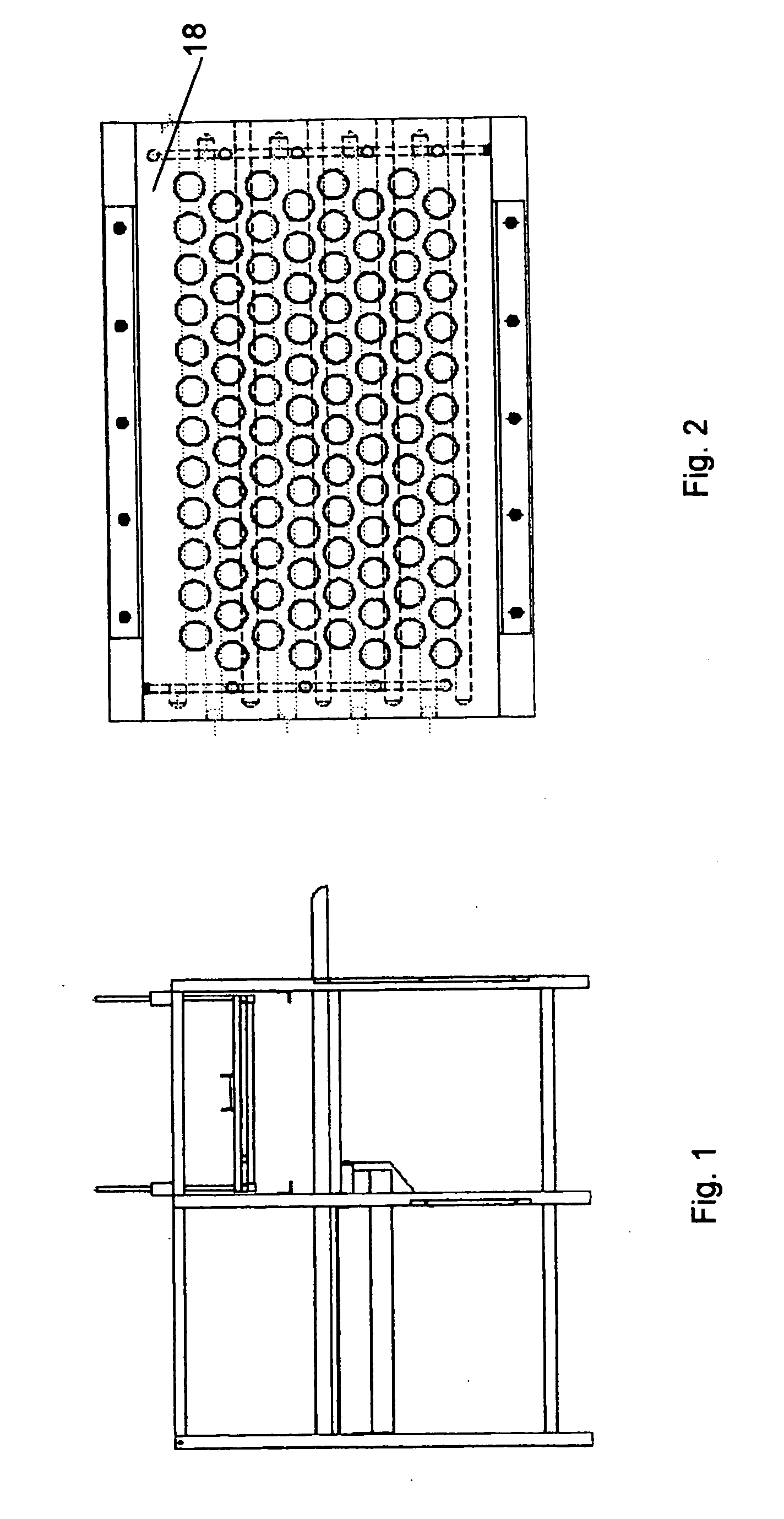
[0040] In accordance with the illustrations above, a tray of fertile eggs is manually introduced into the vaccinator. The movement of the incubator tray through the vaccination process is controlled by three presence sensors. The first sensor detects the incubator tray entering the vaccinator and activates the tray-stop that halts the incubator tray in the correct position below the injection platform.

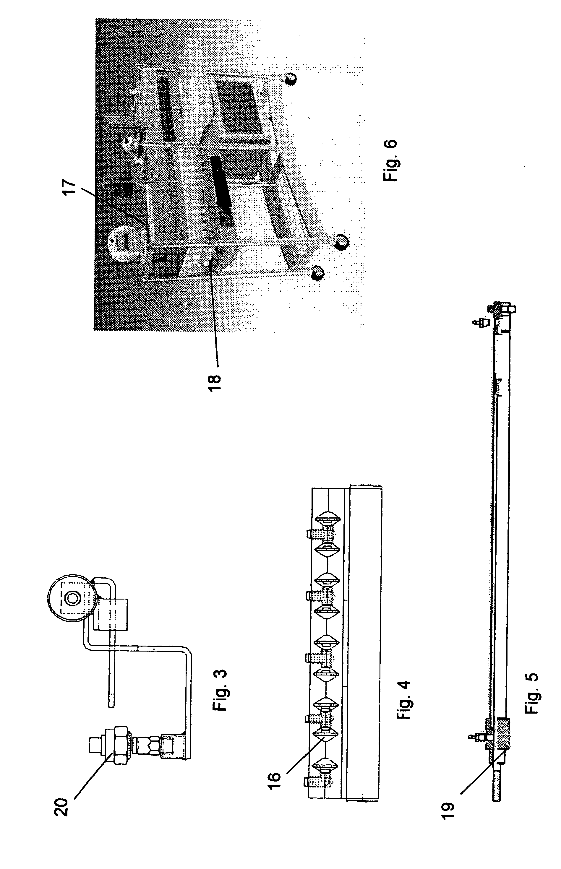
[0041] In this position, the second sensor is activated and a lateral brake is applied to the incubator tray to hold it in position, and the above referred tray-stop is released. The second sensor also activates the injection platform 18, shown in FIG. 2, to lower it over the eggs. A third sensor blocks the action of the first sensor until the tray leaves the vaccination area.

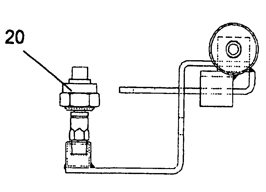
[0042] As injection platform 18 is lowered, the injectors are preferably positioned on top of the eggs. As seen in FIG. 7, the injectors are composed of a cylindrical body 1, and a cap 3 with an electronic conta...


PUM


Abstract

The invention relates to a system of automatic vaccination of eggs, developed for the purpose of vaccinating large quantities of fertile eggs in order to reduce the costs and labor involved, reduce embryonic mortality by increasing protection from diseases and reduce the stress in the first day of life of poultry chicks by eliminating the process of manually vaccinating each chick. The invention comprises an automatic system controlled by a PLC (programmable logic controller), using an injector that has a cylindrical body and cap made from high density non-corrosive plastic and together they form a pneumatic chamber, the cap containing an electronic contact sensor to signal empty egg spaces and avoiding wasting vaccine. The injector's pneumatic chamber contains a plasticized fiber sleeve to permit smooth movement of the pneumatic plunger. A needle passes through the plunger and a double acting spring in addition to securing the plunger in its starting position and returning it to the original position after the injection of vaccine, reduces the pressure on the needle after it breaks the egg shell to avoid harming the embryo. The injection platform that has conical holes for the injectors to permit lateral movements that allows the injectors to accommodate eggs that are tilted, with the injectors locked into position by a series of air bladders located within the platform and running parallel to the injectors. The sanitization system which disinfects the needle and the part of the injector in contact with the egg after every single injection is coupled with the removal of the incubator trays from the vaccination area to economize on production time.

Description

RELATED APPLICATION [0001] This application claims priority from Brazilian Application No. MU8401284-6, filed on Jun. 15, 2004, in Brazil. FIELD OF THE INVENTION [0002] This invention relates to a system of automatic vaccination of eggs. BACKGROUND OF THE INVENTION [0003] The process of vaccinating eggs is important in the medical field and in poultry production. In medicine, eggs are used to incubate biological material utilized in the production of vaccines. In poultry production, the objective of in-egg vaccination is to protect the animals from endemic diseases. [0004] Embryos receiving vaccine three days before hatching instead of the first day after hatching have more time to develop antibodies and consequently have a greater resistance to diseases. In this process, the vaccine ideally is applied directly into the allantoidal cavity of the egg, without direct needle contact with the embryo. [0005] The incubation time for a chicken embryo is typically 21 days and in-egg vaccina...

Claims


Application Information

Patent Timeline
IPC IPC(8): A01K43/00A01K45/00
CPCA01K45/007
Inventor SMITH, DAVID FREDRICK
Owner MERIAL INC
Why Eureka
Try Eureka