
Removing unwanted film from wafer edge region with reactive gas jet

Inactive Publication Date: 2005-12-29
IBM CORP
View PDF8 Cites 27 Cited by
  • Summary
  • Abstract
  • Description
  • Claims
  • Application Information

AI Technical Summary

Benefits of technology

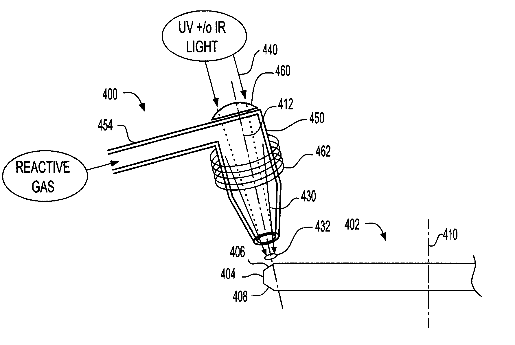
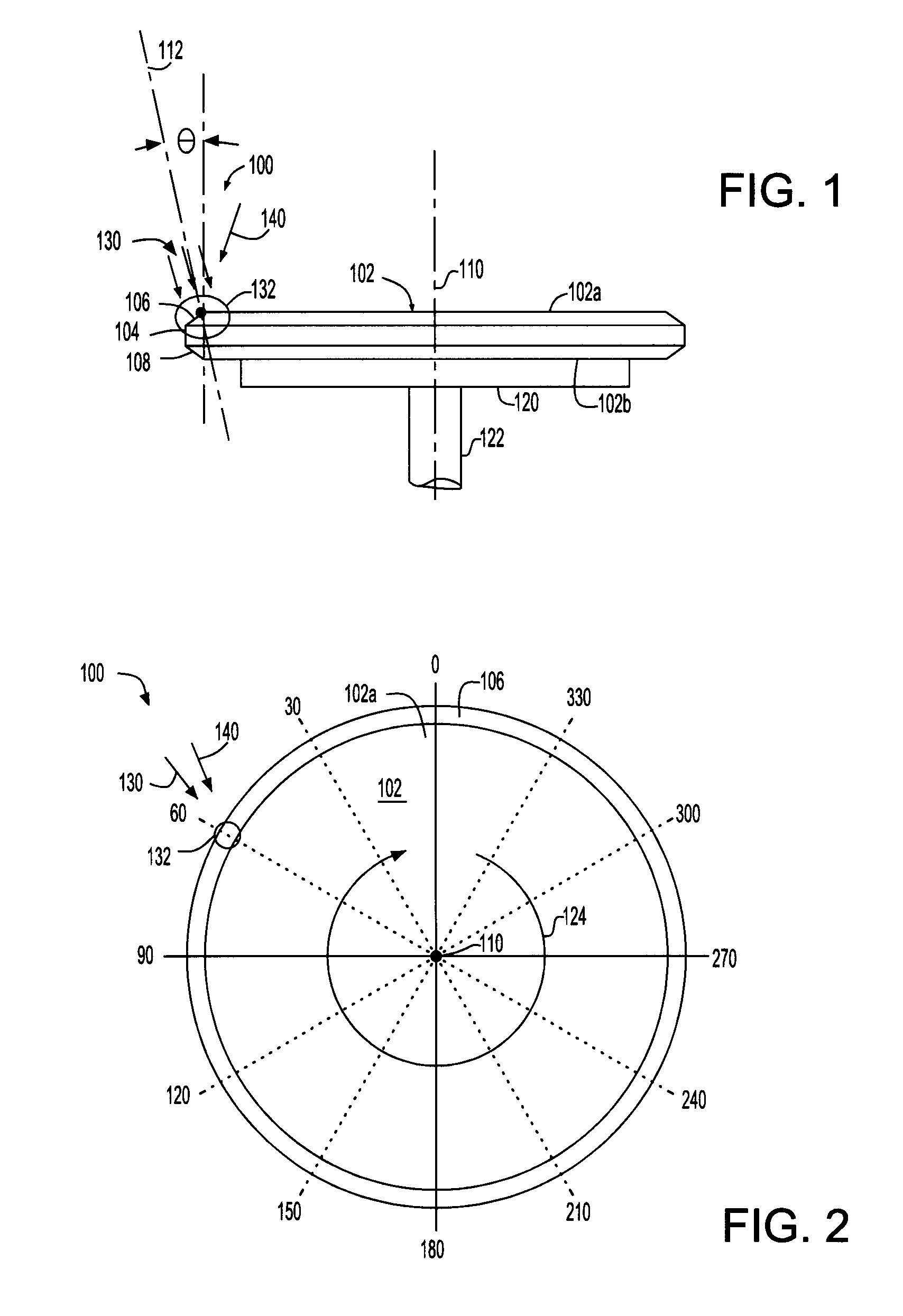
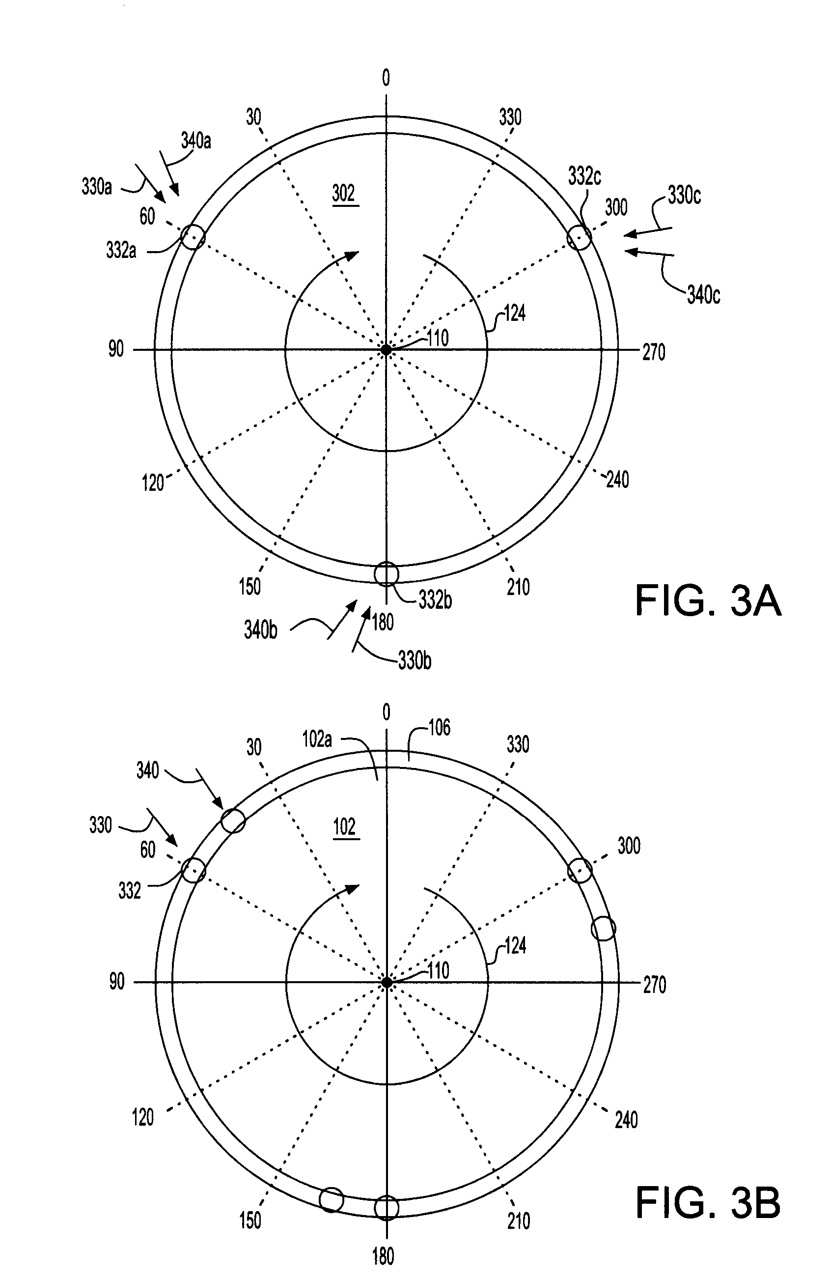
[0010] The present invention provides a process wherein unwanted films deposited during dry etching or created by other semiconductor wafer fabrication processes may be eliminated and / or sculpted (e.g., reduced in thickness) to a preferred profile, by directing a stream of one or more reactive gas(es) at a predefined, small (with respect to the overall wafer) typically substantially circular area (“reactive zone”) which is typically at an edge portion (circumference, periphery, perimeter) of the wafer to remove part or all of the unwanted film, or one of a sequence (stack) of unwanted films. The action of the reactive gas can be enhanced by heating the gas immediately prior to the gas impinging on the wafer. The action of the reactive gas can also be enhanced by a beam of ultraviolet (UV) or infrared (IR) light directed at (e.g., focused upon) or adjacent to the reactive zone. The wafer may be rotated about its center so that the impinging reactive gas(es) and beam(s) of light act on an area encompassing the entire perimeter of the wafer; that is, the “edge region” of the wafer. Alternatively, the wafer can remain stationary, and the gas and light delivery system can be moved around the periphery of the wafer. Multiple gas / light delivery systems can cause gas and light to impinge on multiple reactive zones, both on the front side and on the back side of the wafer.

Problems solved by technology

Consequently, these multiple layers which build up in the edge region can result in high film stress(es) which in turn fracture and result in shards or fragments of the films landing on the device side of the wafer.
These unwanted pieces of foreign matter can result in unwanted defects in the device area of the wafer, reducing performance or device yield.
This film will also build up for each level or wafer processing and result in particulates being released onto the wafer as a result of inherent stress of the film.
Particulates can cause opens in electrical connections and metal lines resulting in product fails.
Wet chemical spray processes have been used to remove polymeric films in the edge region but with limited success owing to limitation of reagents that can be used with acceptable selectivity to the films present.
Most often the plasma power is applied through the full body of the wafer risking unwanted etching of the wafer or plasma induced damage.
Also the plasma processes do not necessarily get to the bevel of the wafer where the unwanted films may have also been deposited.
This is problematic; for example, while oxygen can be made reactive at atmospheric pressure the reactivity at room temperature is low.
This may or may not be acceptable to other films on the wafer.
Also, to remove films other than organic polymers requires gases that usually don not have lifetime sufficiently long outside the plasma to make them reactive with the film to be removed.
Plasma jets also require large amounts of power and are often are difficult to hold stable at atmospheric pressure.

Method used


Image

  • Removing unwanted film from wafer edge region with reactive gas jet
  • Removing unwanted film from wafer edge region with reactive gas jet
  • Removing unwanted film from wafer edge region with reactive gas jet

Examples


Embodiment Construction

[0022] In the description that follows, numerous details are set forth in order to provide a thorough understanding of the present invention. It will be appreciated by those skilled in the art that variations of these specific details are possible while still achieving the results of the present invention. Well-known processing steps are generally not described in detail in order to avoid unnecessarily obfuscating the description of the present invention.

[0023] Materials (e.g., silicon dioxide) may be referred to by their formal and / or common names, as well as by their chemical formula. Regarding chemical formulas, numbers may be presented in normal font rather than as subscripts. For example, silicon dioxide may be referred to simply as “oxide”, chemical formula SiO2. For example, silicon nitride (stoichiometrically Si3N4, often abbreviated as “SiN”) may be referred to simply as “nitride”.

[0024] Exemplary dimensions may be presented for an illustrative embodiment of the invention...


PUM

PropertyMeasurementUnit
Angleaaaaaaaaaa
Areaaaaaaaaaaa
Transparencyaaaaaaaaaa

Abstract

Unwanted films can be eliminated by directing a stream of reactive gas(es) at reactive zone in an edge region of the wafer. The action of the reactive gas can be enhanced by heating the gas in a nozzle, immediately prior to the gas impinging on the wafer. The action of the reactive gas can also be enhanced by ultraviolet (UV) or infrared (IR) radiation directed at the reactive zone. The wafer is rotates so that the reactive zone traverses the entire edge region. Multiple gas / light delivery systems can cause gas and light to impinge on multiple reactive zones, both on the front side and on the back side of the wafer.

Description

BACKGROUND OF INVENTION [0001] The invention relates to semiconductor device fabrication, and more particularly to techniques for removal of residual process films (e.g., polymeric and refractory films) and debris from the edge region (perimeter and bevel) of a semiconductor wafer. [0002] Semiconductor wafers are typically round (circular, disc-like), usually having a diameter ranging from 150-350 mm and a thickness of 1-1.5 mm. Integrated circuit (IC) devices are formed in an interior “device area” on the front (or device) side of the wafer. The edge (perimeter) of the wafer is often beveled, typically at 45 degrees, the bevel extending approximately 0.5-1.0 mm from the edge of the wafer towards the center of the wafer. An “edge region” of the wafer includes the edge of the wafer, the bevel, and a small (e.g., 0.5-2.0 mm on the front side, 0.5-4.0 mm region on the back side) area within the bevel. [0003] A semiconductor wafer that has been processed in a typical manner can have und...

Claims


Application Information

Patent Timeline
IPC IPC(8): B08B7/00B44C1/22C23F1/00H01L21/00
CPCH01L21/6708B08B7/0057
Inventor AMERICA, WILLIAM GEORGEJOHNSTON, STEVEN HILTON
Owner IBM CORP
Learn More