Photoconductor, image forming process, image forming apparatus, and process cartridge

a photoconductor and image forming technology, applied in the direction of electrographic process, corona discharge, instruments, etc., can solve the problems of higher wear rate of photoconductors, less durability of organic photoconductors, and high surface layer wear, so as to achieve excellent flaw resistance, appropriate electric properties, and superior wear resistance

Inactive Publication Date: 2005-12-29
RICOH KK
View PDF26 Cites 62 Cited by
  • Summary
  • Abstract
  • Description
  • Claims
  • Application Information

AI Technical Summary

Benefits of technology

[0019] The object of the present invention is to provide photoconductors that can exhibit superior wear resistance, excellent flaw resistance, and appropriate electric properties, more specifically, proper cleaning ability, higher durability, and higher

Problems solved by technology

However, organic photoconductors are typically less durable since the hardness of the surface layers is relatively low due to their inherent components of charge transport substances of lower molecular mass and inactive polymers; therefore, the surface layers tend to wear significantly due to mechanical stress caused by developing systems and cleaning systems etc. under repeated usages in electrophotographic processes.
Further, rubber hardness of cleaning blades has been raised and pressure onto photoconductors applied from the cleaning blades has been increased so as to improve cleaning ability in order to enhance image quality by using toner particles with smaller particle sizes, which inevitably leading to higher wear rate of photoconductors.
The wear of photoconductors certainly degrades sensitivity, electric properties such as charging ability etc., which resulting in deteriorated images such as lower image density and background smear.
Further, flaws due to local wear often bring about streak on images due to insufficient cleaning.
Such wear and flaws typically dominate photoconductors in terms of lifetime to be exchanged, currently.
However, in the (i) incorporation of curable binders described above, residual voltage tends to increase owing to impurities such as polymerization initiators and/or unreacted residual groups due to insufficient compatibility with charge transport substances, thus image density tents to decrease; in the (ii) employment of polymers for charge transport substances described above, the durability cannot be sufficiently improved for satisfying the requirements for organic photoconductors; moreover, electric properties of organic photoconductors are likely to be unstable since polymers for charge transport substances are difficult to be polymerized and purified, and also coating liquids of them are typically excessively viscous to be processed.
However, traps on the surface of the inorganic fillers tend to increase residual potential, thereby causing decrease in the image density.
Also, when unevenness of the photoconductor surface is significant due to the inorganic filler and the binder resin, cleaning may be insufficient, resulting in toner filming and image deletion.
As such, based on these proposals (i), (ii), and

Method used


Image

  • Photoconductor, image forming process, image forming apparatus, and process cartridge
  • Photoconductor, image forming process, image forming apparatus, and process cartridge
  • Photoconductor, image forming process, image forming apparatus, and process cartridge

Examples


example 1

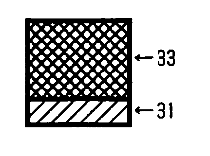
[0225] On an aluminum cylinder of 30 mm in diameter, the coating liquid for undercoat layer, the coating liquid for charge generating layer, and the coating liquid for charge transport layer, each having the composition described below, were sequentially applied and dried to form an undercoat layer of 3.5 μm thick, a charge generating layer of 0.2 μm thick, and a charge transport layer of 18 μm thick.

[0226] Then, the coating liquid for crosslinked layer having the following composition was coated over the charge transport layer by spray coating, and the coating was subjected to optical irradiation using a metal halide lamp of 160 W / cm under the conditions of 120 mm from the light source, 500 mW / cm2 of irradiation energy, and 30 seconds of irradiating period, and then was subjected to heating at 130° C. for 20 minutes, thereby yielded a crosslinked layer of 4 μm thick and the inventive photoconductor was obtained.

[0227] [Coating Liquid for Undercoat Layer]

Alkyde resin 6 parts(Becko...

example 2

[0231] A photoconductor was produced in the same manner as Example 1, except that the radical polymerizable monomer having three or more functionalities and no charge transport structure in Example 1 was changed into the monomer described below.

Radical polymerizable monomer having three or more10 partsfunctionalities and no charge transport structureDimethylolpropane tetraacrylate (SR-355, by Kayaku SartomerCo.), molecular mass: 466, number of functional group: four,molecular mass / number of functional group = 117

example 3

[0232] A photoconductor was produced in the same manner as Example 1, except that the radical polymerizable monomer having three or more functionalities and no charge transport structure, the photopolymerization initiator, and the thermal polymerization initiator in Example 1 were changed into those described below.

Radical polymerizable monomer having three or more10 partsfunctionalities and no charge transport structurePentaerythritol tetraacrylate (SR-295, by Kayaku Sartomer Co.)molecular mass: 352, number of functional group: four,molecular mass / number of functional group = 88Photopolymerization initiator 2 parts2,2-dimethoxy-1,2-diphenylethane-1-one(IRGACURE 651, by Ciba Specialty Chemicals Co.)Thermal polymerization initiator 2 partst-butyl-peroxy-2-ethylhexanoate (Kayaester O, by Kayaku AkzoCo.)


PUM

PropertyMeasurementUnit
Percent by massaaaaaaaaaa
Massaaaaaaaaaa

Abstract

A photoconductor is disclosed that exhibits superior wear resistance, excellent flaw resistance, and appropriate electric properties owing to a photosensitive layer having a crosslinked layer with superior smoothness and higher crosslink density, wherein the photoconductor comprises a support, and a photosensitive layer disposed on the support, the photosensitive layer comprises a crosslinked layer, the crosslinked layer comprises a radical polymerizable monomer having three or more functionalities and no charge transport structure and a radical polymerizable compound having one functionality and a charge transport structure, and the crosslinked layer is cured by way of photopolymerization and thermal polymerization.

Description

BACKGROUND OF THE INVENTION [0001] 1. Field of the Invention [0002] The present invention relates to photoconductors that can provide higher image quality for prolonged period, owing to photosensitive layers that can exhibit superior wear resistance, excellent flaw resistance, and appropriate electric properties; and image forming processes, image forming apparatuses, and process cartridges that utilize the photoconductors respectively. [0003] 2. Description of the Related Art [0004] Recently, organic photoconductors (OPC) are widely employed in copiers, facsimiles, laser printers, and composite apparatuses thereof owing to excellent performance and various advantages, in place of conventional inorganic photoconductors. Specific grounds thereof are thought as follows: (i) optical properties such as absorbable wavelength and absorption rate, (ii) electrical properties such as higher sensitivity and stable charging ability, (iii) margins of materials, (iv) productivity, (v) lower cost...

Claims


Application Information

Patent Timeline
IPC IPC(8): G03G5/047G03G5/05G03G5/06
CPCG03G5/0542G03G5/0553G03G5/0614G03G5/0592G03G5/0589
Inventor TAMURA, HIROSHIIKUNO, HIROSHIYANAGAWA, YOSHIKISUZUKI, TETSUROKAWASAKI, YOSHIAKITODA, NAOHIRO
Owner RICOH KK
Why Eureka
Try Eureka