
Method for enhancing mobility of working fluid in liquid/gas phase heat dissipating device

Inactive Publication Date: 2006-01-12
IND TECH RES INST
View PDF13 Cites 22 Cited by
  • Summary
  • Abstract
  • Description
  • Claims
  • Application Information

AI Technical Summary

Benefits of technology

[0010] The primary objective of the present invention is to improve the mobility of the working fluid in a liquid / gas phase heat dissipating device and further enhance the heat dissipation capability of the heat dissipating device.
[0011] To achieve the foregoing objective, the present invention utilizes the method of changing the property of the surface of a liquid / gas phase heat dissipating device to coat a layer of material on the surface of the capillary structure, and the coating method could be by sputting, plating, electroplating, electronform or chemical vapor disposition (CVD) and the coating material could be any one selected from copper, iron, zinc, aluminum, nickel, and chromium, so that the contact angle between the working fluid and the capillary structure according to the present invention is smaller than that of the prior-art device, and thus the working fluid has a better adhesion with the capillary structure in the sealed cavity as well as a better mobility for the fluid, and further gives a better heat dissipation effect.

Problems solved by technology

The reduced size also increases the quantity of electronic components per unit volume, and thus results in a trend of giving out heat in a high thermal flux density.
Since the operating temperature of an electronic component is closely related to the reliability and the life of the electronic component, therefore the way of effectively enhancing the heat dissipating capability becomes a key issue, particularly in the field of electronic peripherals of notebook computers that is restricted by volume and size.
If other methods are used to enhance the capillary tension such as changing the size of the capillary structure or eliminating the impurities on the surface, the cost for the manufacturing technology and expenditure required for such change will be increased.
Even after the size of the capillary structure is accomplished, the contact angle between the surface of the capillary structure becomes smaller, but the property of the basic material of the surface of the capillary structure is still not improved, and thus the mobility of the working fluid has not been improved thoroughly.
However, the general rinsing procedure takes lots of manpower, and if related chemical rinsing agents such as a pickling or an organic solvent are used for the rinse, such arrangement not only increases the cost,-but also contaminates the environment.
Most importantly, the oxidation capability after the rinse is not good.
Besides the size and arrangement of the capillary structure, there is no significant improvement on the property of the surface of the capillary structure.
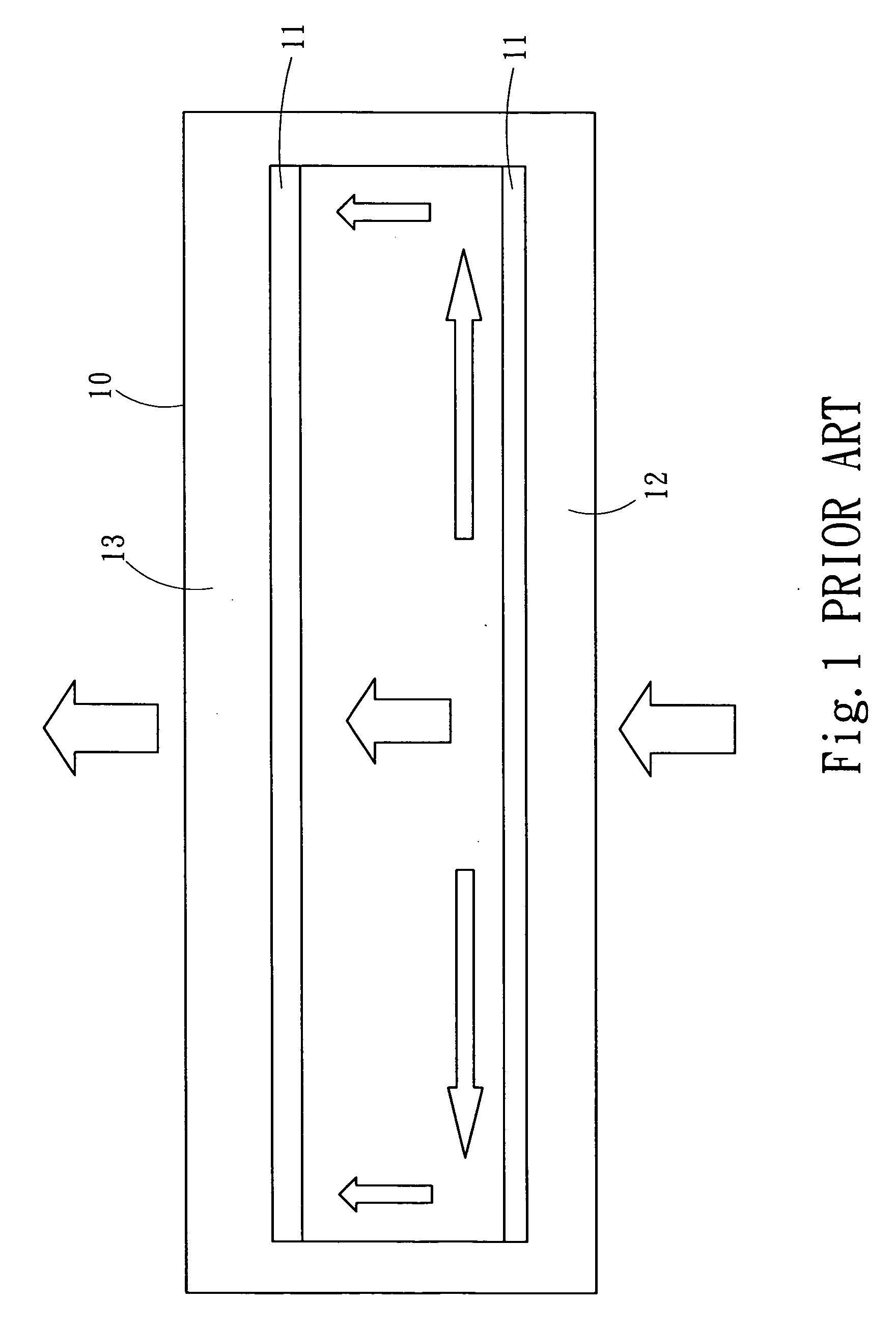
However, the foregoing prior arts did not teach how to improve the surface contact of the working fluid and the capillary structure.

Method used


Image

  • Method for enhancing mobility of working fluid in liquid/gas phase heat dissipating device
  • Method for enhancing mobility of working fluid in liquid/gas phase heat dissipating device
  • Method for enhancing mobility of working fluid in liquid/gas phase heat dissipating device

Examples


Embodiment Construction

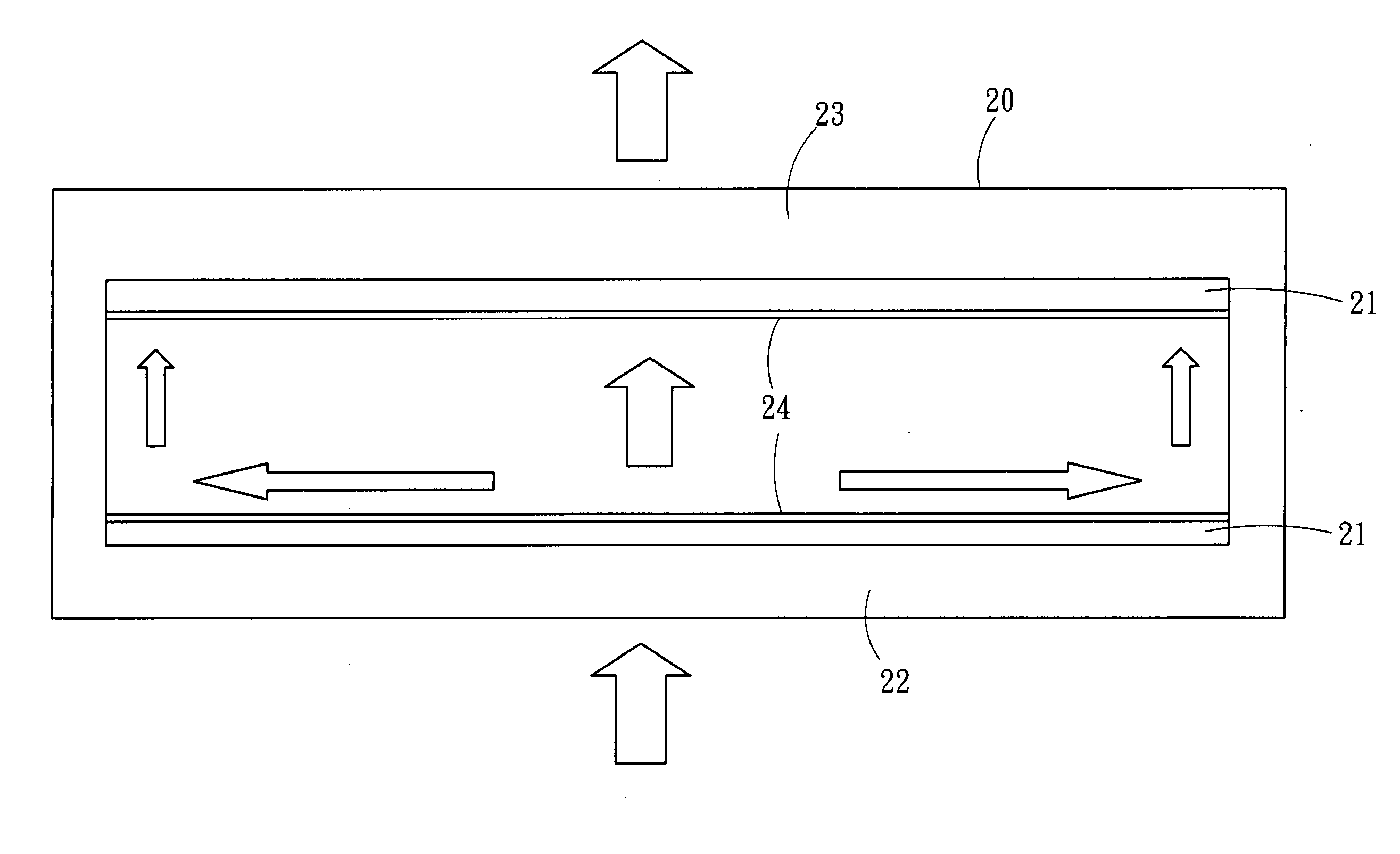
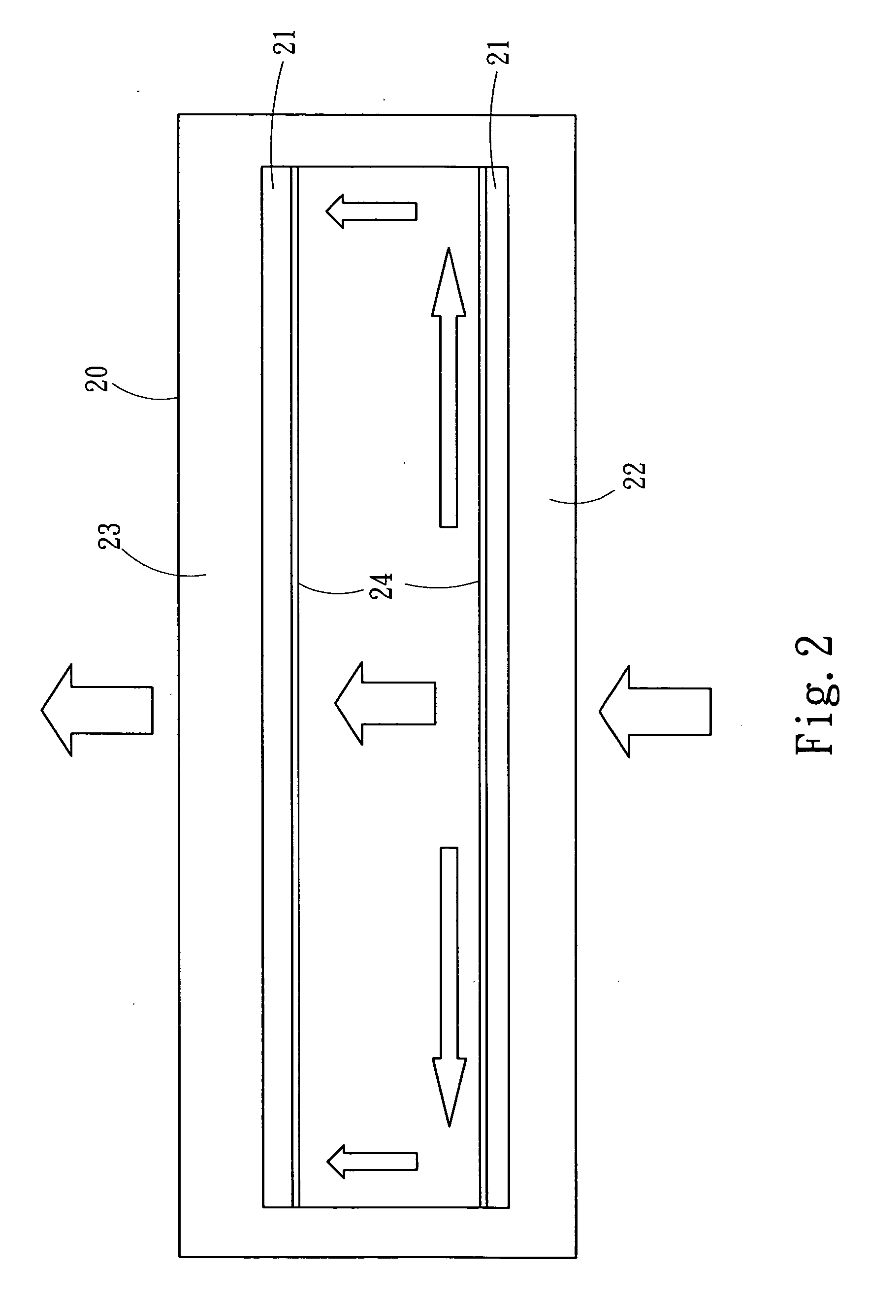
[0020] Please refer to FIG. 2 for the cross-sectional view of the liquid / gas phase heat dissipating device according to the present invention. The heat dissipating device is a sealed metal cavity 20 containing a capillary structure layer 21, and a hydrophilic layer 24 coated on the surface of the capillary structure layer 21 and the coating methods include but not limited to sputting, plating, electroplating, electronform, and chemical vapor deposition (CVD), etc. The hydrophilic layer 24 is made of any one of the materials selected from iron, zinc, aluminum, nickel and chromium. The sealed metal cavity 20 has a heated end (vaporizing end) 22 and a cooling end (condensing end) 23. The sealed metal cavity 20 contains a working fluid, and the working fluid could be a fluid selected from pure water, ammonia solution, methyl alcohol, ethyl alcohol and acetone which has a high mobility and absorbs a large quantity of heat during the evaporation.

[0021] The principle of heat dissipation i...


PUM

PropertyMeasurementUnit
Lengthaaaaaaaaaa
Nanoscale particle sizeaaaaaaaaaa
Hydrophilicityaaaaaaaaaa

Abstract

A method for enhancing the mobility of a working fluid in a liquid / gas phase heat dissipating device improves the mobility of the working fluid therein, and further enhancing the heat dissipation capability of the heat dissipating device. The present invention coats a layer on the surface of a capillary structure inside the heat dissipating device to increase the material property on the surface and the coupling force between the working fluid and the capillary structure and decrease the contact angle between the working fluid and the capillary structure, and thus the working fluid has a higher mobility to solve the problem of the high heat flux density of the liquid / gas heat dissipating device and improve the heat dissipation effect. The present invention not only applies to the heat generating electronic components within a limited space, but also applies to other electronic components that require a constant temperature.

Description

FIELD OF THE INVENTION [0001] The present invention relates to a method for manufacturing a fluid phase heat dissipating device, more particularly to a method of enhancing the mobility of a working fluid in a liquid / gas phase heat dissipating device. BACKGROUND OF THE INVENTION [0002] With the requirements of high performance and high efficiency, the operating frequency of electronic components is getting larger and larger. As a result, the quantity of heat so produced is increasing day after day. However, the advancement of science and technology makes electronic products to follow the trend of a light, thin, short and compact design. The reduced size also increases the quantity of electronic components per unit volume, and thus results in a trend of giving out heat in a high thermal flux density. Since the operating temperature of an electronic component is closely related to the reliability and the life of the electronic component, therefore the way of effectively enhancing the h...

Claims


Application Information

Patent Timeline
IPC IPC(8): F28D15/00
CPCF28D15/046F28F13/18F28F2245/02Y10T29/49353H01L2924/0002H01L23/427H01L2924/00
Inventor YEH, LAN-KAILIN, CHE-WEICHEN, SHAO-WENSHYU, JIN-CHERNGTSAI, MING-JYE
Owner IND TECH RES INST
Learn More