
High temperature gas separation membrane suitable for OBIGGS applications

a gas separation membrane and high temperature technology, applied in the field of gas separation membranes, can solve the problems of increasing the risk of fuel tank composition, flame propagation or explosion, and each of these approaches has proved costly to operate or is being eliminated

Inactive Publication Date: 2006-01-19
HONEYWELL INT INC
View PDF15 Cites 42 Cited by
  • Summary
  • Abstract
  • Description
  • Claims
  • Application Information

AI Technical Summary

Benefits of technology

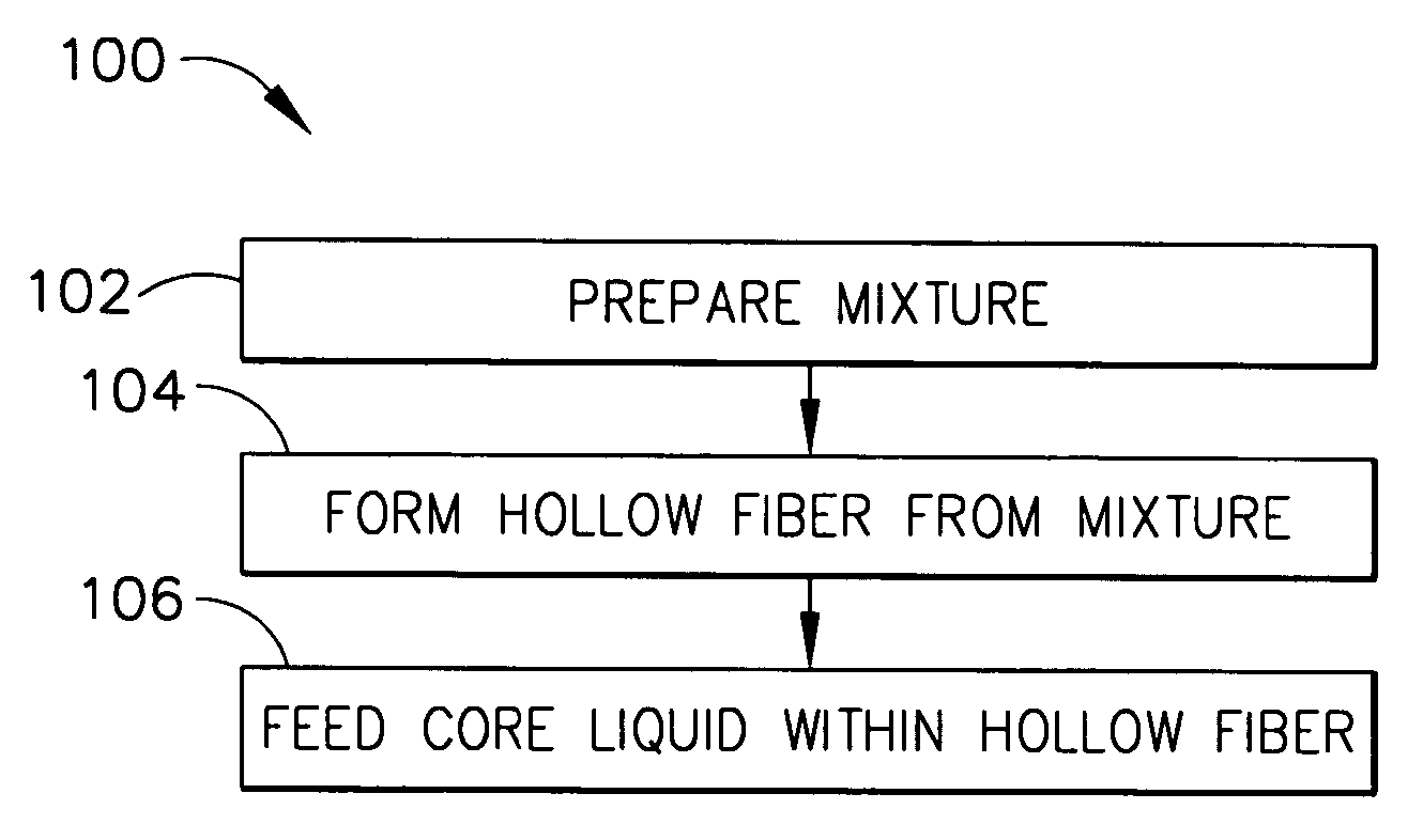
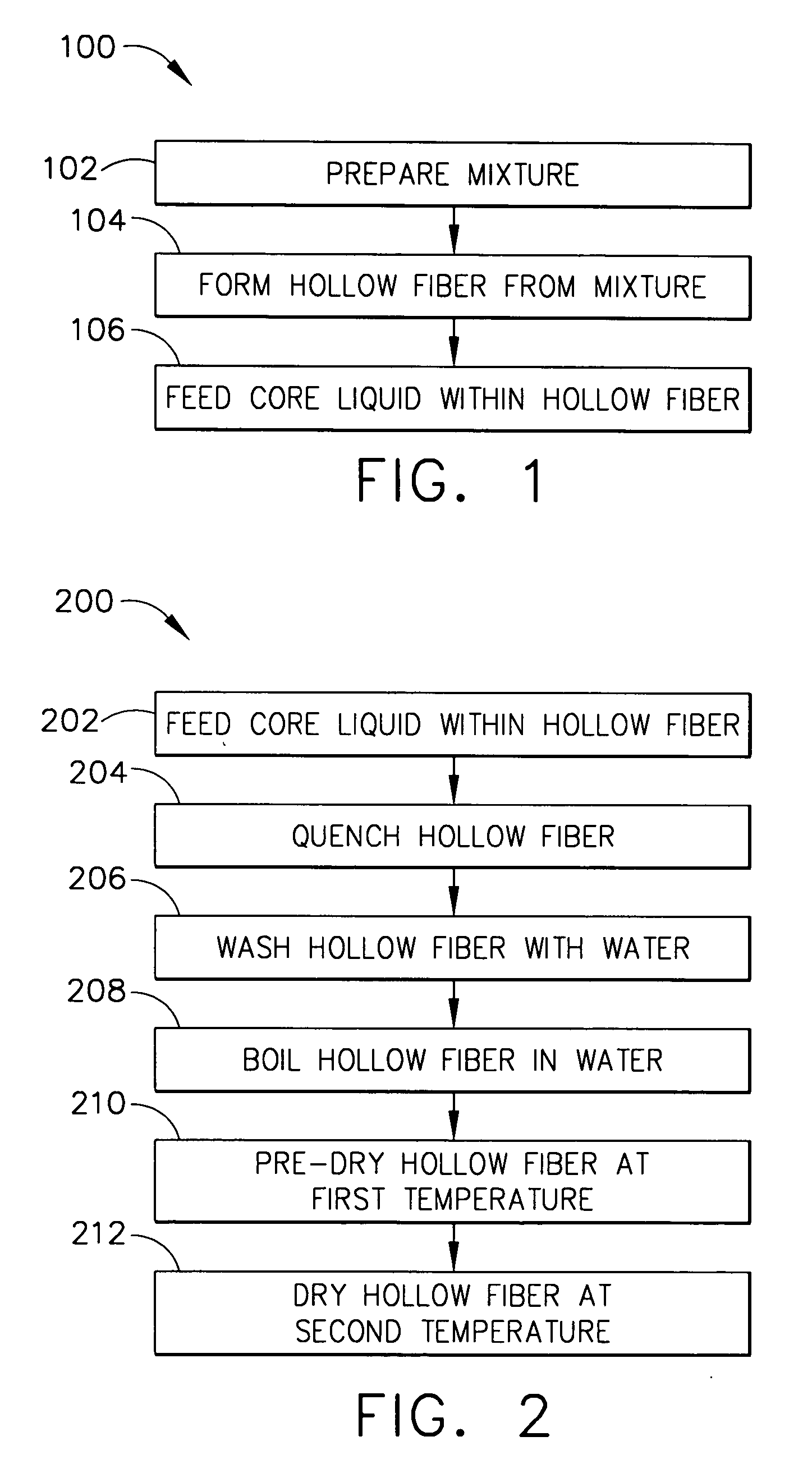
[0008] In one aspect of the present invention, there is provided a method for preparing a high temperature gas separation membrane comprising preparing a mixture, wherein the mixture comprises a polymer, a solvent, and a non-solvent; forming a hollow fiber from the mixture; and feeding a core liquid within the bore of the hollow fiber. The membrane is heat stable to a temperature of at least about 160° C., and the membrane has an oxygen / nitrogen selectivity of at least about 2.

Problems solved by technology

Aircraft manufacturers are becoming increasingly sensitive to the risks associated with the composition of fuel tank ullage.
This is due to risk of flame propagation or explosion when a mixture of fuel vapors and air occupy fuel tank ullage, for example, as fuel is consumed during flight.
Each of these approaches has proved costly to operate or is being eliminated due to environmental concerns.
Conventional gas separation membranes have a maximum operating temperature of about 90° C. Such gas separation membranes cannot withstand exposure to bleed air fed to an OBIGGS.

Method used


Image

  • High temperature gas separation membrane suitable for OBIGGS applications
  • High temperature gas separation membrane suitable for OBIGGS applications
  • High temperature gas separation membrane suitable for OBIGGS applications

Examples


example 1

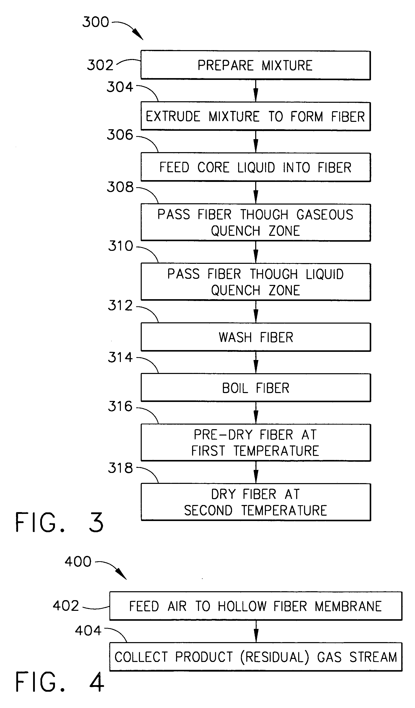
[0056] A mixture of 30% by weight polyetherimide (PEI), 58.2% by weight N-methyl pyrrolidone (NMP, solvent), and 11.8% by weight ethanol (non-solvent), (solvent to non-solvent ratio of 4.9) was placed in a 500 ml plastic bottle and shaken at 100 rpm on a reciprocating shaker at 70° C. overnight. The mixture was then de-bubbled and extruded through a spinnerette at a rate of 1.9 g / min. The mixture was kept at 90° C. and the surface of the spinnerette was kept at 75° C. The mixture was extruded through an annulus (684 microns inside diameter and 1194 microns outside diameter) with a core fluid pin feeding a core liquid comprising 42% by weight NMP and 58% by weight ethanol at a rate of 0.9 ml / min. The line speed was 120 ft / min. The extruded hollow fiber was passed through an air quench zone having a height of 25 cm. at ambient temperature. The fiber was then passed through a liquid quench bath of ambient temperature tap water with a residence time of 2 seconds. The fiber was wound on ...

example 2

[0058] A mixture of 40% by weight polyetherimide (PEI), 47.4% by weight N-methyl pyrrolidone (NMP, solvent), and 12.6% by weight triethylene glycol (TEG, non-solvent), (solvent to non-solvent ratio of 3.8) was placed in a 2000 ml stirred reactor and stirred at 80° C. for 48 hours. The mixture was then de-bubbled and extruded through a spinnerette at a rate of 2.2 g / min. The mixture was kept at 90° C. and the surface of the spinnerette was kept at 97.5° C. The mixture was extruded through an annulus (684 microns inside diameter and 1194 microns outside diameter) with a core fluid pin feeding a core liquid comprising 50% by weight NMP and 50% by weight TEG at a rate of 1.0 ml / min. The line speed was 200 ft / min. (about 60 m / min.). The extruded hollow fiber was passed through an air quench zone having a height of 40 centimeters at ambient temperature. The fiber was then passed through a liquid quench bath of ambient temperature tap water with a residence time of 1.2 seconds. The fiber w...

example 3

[0060] A polyetherimide hollow fiber gas separation membrane prepared according to the instant invention (e.g., as described hereinabove with respect to FIGS. 1-3) was exposed to a temperature of 150° C., and the inlet flow rate, product flow rate, and permeate flow rate were recorded over time. On the date shown as 1 / 20 (FIG. 5A), the temperature was raised to 160° C., and thereafter the temperature was maintained at 160° C. The inlet flow rate, product flow rate, and permeate flow rate were essentially constant over the following 34 days. The results shown in FIG. 5A indicate that the hollow fiber of the instant invention is stable at temperatures of at least about 160° C.


PUM

PropertyMeasurementUnit
temperatureaaaaaaaaaa
inside diameteraaaaaaaaaa

Abstract

Gas separation membranes and methods for preparing such membranes. The gas separation membranes of the instant invention can separate oxygen and nitrogen in air to provide nitrogen enriched air (NEA), and are stable during exposure to temperatures of at least about 160° C. The gas separation membranes of the instant invention may be formed from polyetherimide by extruding a hollow fiber using a core liquid, quenching the extruded fiber in dry air to promote loss of solvent and non-solvent, and drying the fiber. Methods for separating bleed air fed directly from an aircraft precooler to a high temperature gas separation hollow fiber membrane, to provide NEA, are also disclosed.

Description

BACKGROUND OF THE INVENTION [0001] The present invention generally relates to gas separation membranes, and to methods for preparing such membranes. [0002] Separation of gaseous components of a gas mixture may be achieved by various processes, including pressure swing adsorption, cryogenics, and membrane separation. Membrane separations are based on the relative permeability of the various gaseous components in the gas mixture to be separated through the membrane material. For example, in the case of separation of gaseous components of air, separation may be based on the relative permeability of the membrane to oxygen and nitrogen. [0003] Aircraft manufacturers are becoming increasingly sensitive to the risks associated with the composition of fuel tank ullage. This is due to risk of flame propagation or explosion when a mixture of fuel vapors and air occupy fuel tank ullage, for example, as fuel is consumed during flight. The risk of explosion can be greatly decreased by providing ...

Claims


Application Information

Patent Timeline
Patent Type & Authority Applications(United States)
IPC IPC(8): B01D53/22
CPCB01D53/228B01D67/0011B01D67/0016B01D2325/22B01D71/64B01D2257/104B01D2323/22B01D69/08B01D71/643B01D67/00113
Inventor ZHOU, SHAOJUN J.
Owner HONEYWELL INT INC
Learn More