Reduced pressure irradiation processing method and apparatus

a processing method and a technology of reduced pressure, applied in the direction of cleaning processes and apparatus, chemistry apparatus and processes, liquid cleaning, etc., can solve the problems of unsatisfactory end result requirements, and inability to achieve optimal end result requirements

Inactive Publication Date: 2006-01-26
AKRION TECH +1
View PDF22 Cites 24 Cited by
  • Summary
  • Abstract
  • Description
  • Claims
  • Application Information

AI Technical Summary

Benefits of technology

[0012] The optional ultraviolet transmissive window is preferably made of fluorinated glass or sapphire. The UV light box may contain a reflector for providing uniform ultraviolet radiation transmission.
[0013] The controller may activates components for creating a cleaning gas atmosphere upon activating the components for reducing pressure, thereby backfilling the first module with cleaning gas as undesirable gases are removed.

Problems solved by technology

However, existing systems are less than optimal in that the processing takes too long or does not achieve optimal end result requirements.
There are several reasons why the use of supercritical fluid drying is undesirable, and there are also reasons why the use of 100-200° C. temperature in a low pressure drying chamber is undesirable, for example at such high temperatures sodium, lithium, potassium, and / or other ions can migrate.

Method used


Image

  • Reduced pressure irradiation processing method and apparatus
  • Reduced pressure irradiation processing method and apparatus
  • Reduced pressure irradiation processing method and apparatus

Examples


Embodiment Construction

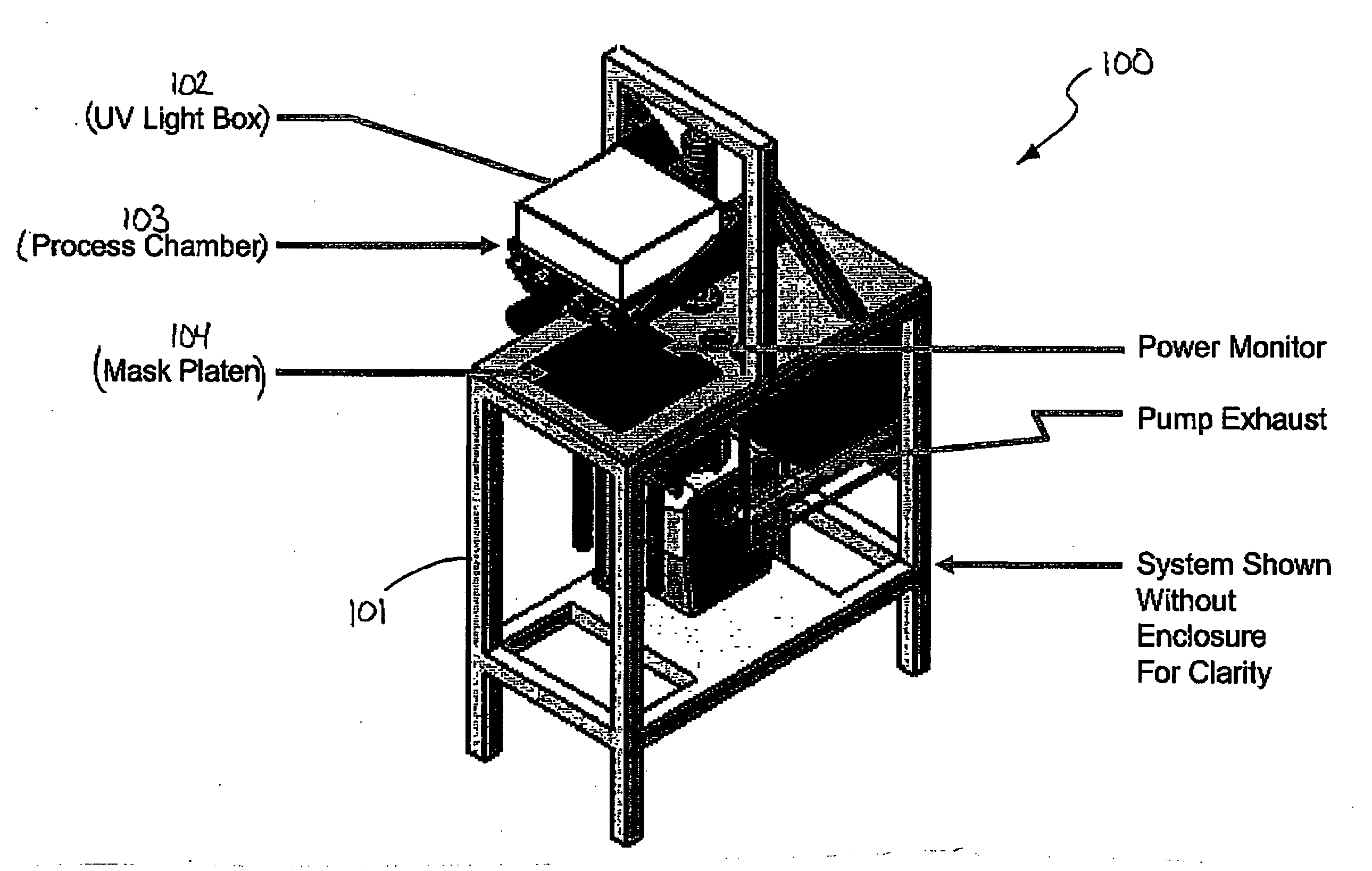
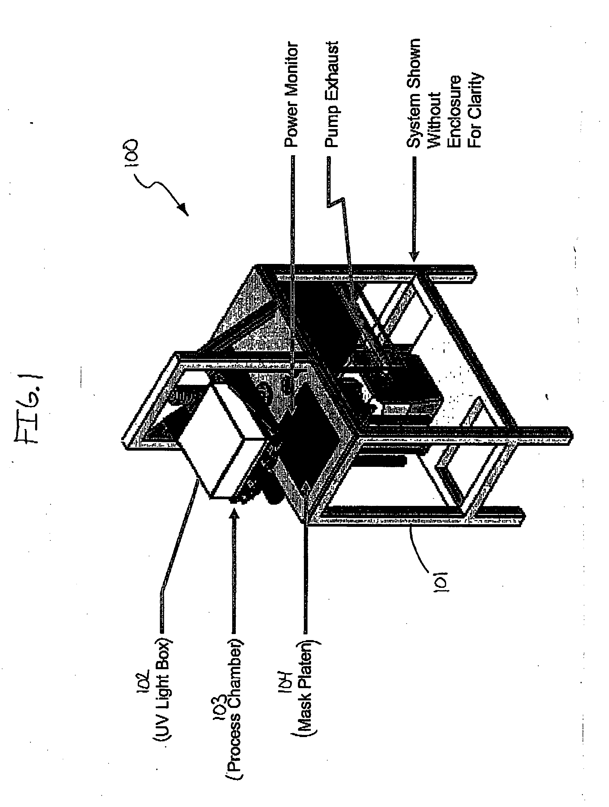
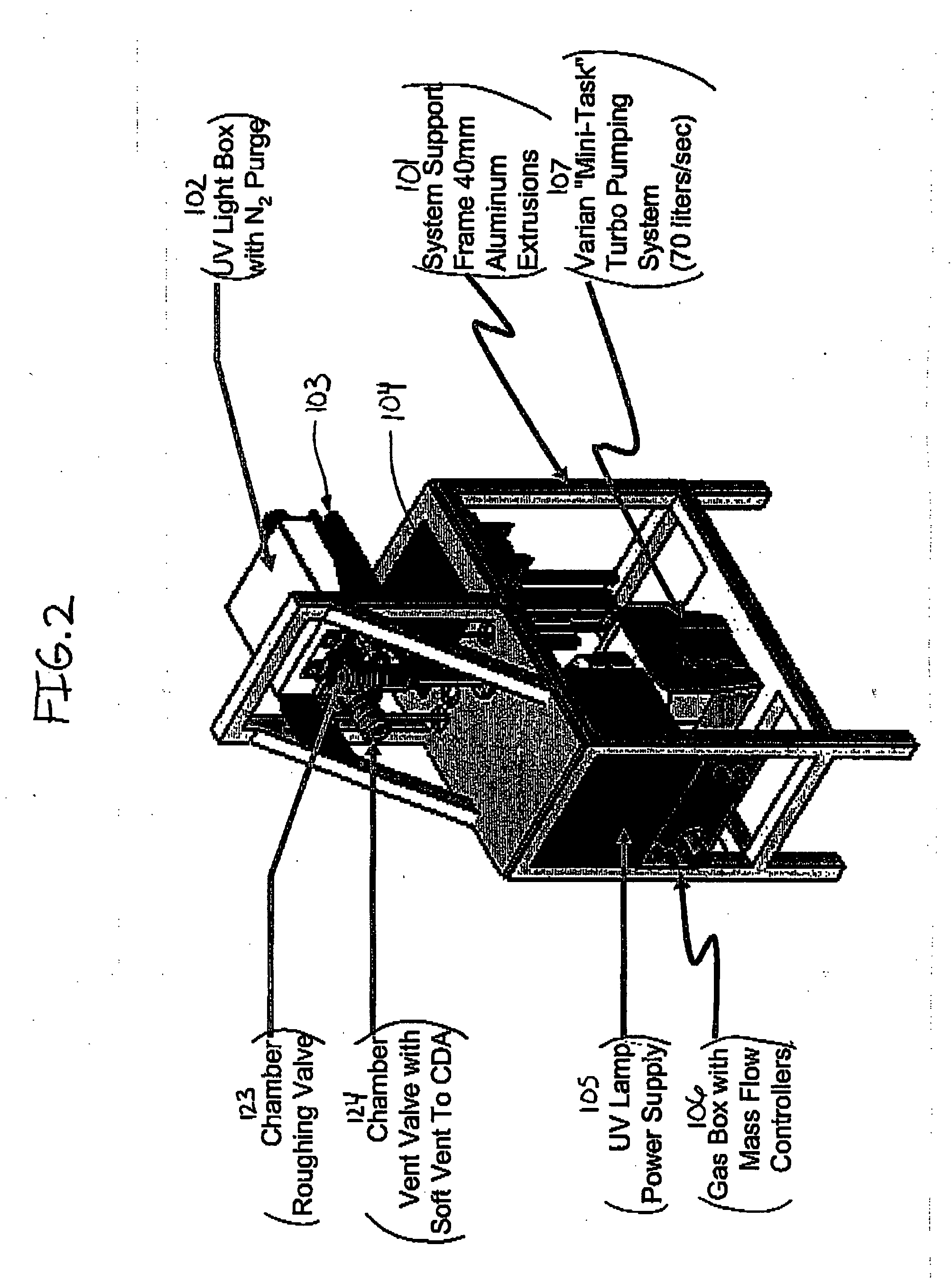
[0034]FIGS. 1 and 2 schematically illustrate a one UV drying module 100 embodiment of the present invention. The substrate process apparatus 100 comprises a support frame assembly 101 that supports the various components for operating the apparatus, including an ultraviolet (“UV”) light box 102, a substrate process chamber 103, a mask platen 104, an ultraviolet lamp power supply 105, a gas box 106 containing mass flow controllers, and a pumping system 109. Substrate process system 100 is a two chamber system for the purpose of irradiating photomask, reticle substrates, and semiconductor substrates with ultraviolet radiation in a reduced pressure environment for the purposes of removing contamination in the form of residual films and particles. Substrate process system 100 comprises a substrate process chamber 103 and a separate UV chamber 127 (shown in FIG. 4). The substrate process chamber 103 and the UV chamber 127 are substantially vertically aligned, wherein the UV chamber 127 i...


PUM


Abstract

A system and method for processing substrates, such as porous low-K semiconductor wafers, using ultraviolet (UV) radiation is disclosed. The substrates are first cleaned in a wet processing module and then dried in a UV module under reduced pressure and at a temperature below 100 C., preferably at or below 80 C. A robot module transfers the substrates from the wet processing module to the UV module. The UV module can include a pulse xenon excimer lamp providing incoherent vacuum ultraviolet (VUV) radiation at 172 nm.

Description

CROSS-REFERENCE TO RELATED APPLICATIONS [0001] The present application claims the benefit of U.S. Provisional Application Ser. No. 60 / 586,773, filed Jul. 9, 2004, the entirety of which is incorporated herein by reference.BACKGROUND OF THE INVENTION [0002] The present invention relates generally to systems and methods for processing substrates, especially systems and methods for cleaning and / or drying silicon wafer or photomask substrates. The invention also relates to single wafer cleaning and drying methods and apparatus. [0003] The use of ultraviolet radiation during various substrate processing steps, such as the removal of organic compounds or cleaning, is known. However, existing systems are less than optimal in that the processing takes too long or does not achieve optimal end result requirements. [0004] Single wafer wet processing systems have become available and are being used commercially, among which are the “Goldfinger” single wafer megasonic cleaning system, “Sahara” si...

Claims


Application Information

Patent Timeline
Patent Type & Authority Applications(United States)
IPC IPC(8): B08B3/00
CPCB08B7/0057H01L21/67028H01L21/67207H01L21/67115H01L21/67173H01L21/67034
Inventor NOVAK, RICHARDMONKO, ROBERT S.MARSHALL, GLENN
Owner AKRION TECH
Why Eureka
Try Eureka