High-frequency oscillator, high-frequency transmission-reception apparatus using the same, radar apparatus, and radar-apparatus-equipped vehicle and small boat equipped with the same

a technology of transmission and transmission, which is applied in the direction of oscillator, instrument, measurement device, etc., can solve the problems of difficult to stably obtain the desired oscillation characteristics and difficult to obtain stably good transmission-reception performance, and achieve the effect of stably and good oscillation characteristics

Inactive Publication Date: 2006-01-26
KYOCERA CORP
View PDF12 Cites 11 Cited by
  • Summary
  • Abstract
  • Description
  • Claims
  • Application Information

AI Technical Summary

Benefits of technology

[0015] In consideration of the abovementioned circumstances, an object of the invention is to provide a high-frequency oscillator that can tune oscillation characteristics such as an oscillation frequency and a frequency modulation width with a bias supply circuit of a variable-capacitance element as a component of the high-frequency oscillator and can stably exhibit good oscillation characteristics, and provide a high-performance high-frequency transmission-reception apparatus using the high-frequency oscillator.

Problems solved by technology

However, the conventional high-frequency oscillator and the high-frequency oscillators as disclosed in JP-A 6-268445 (1994), JP-A 6-268446 (1994), JP-A 6-268447 (1994) and JP-A 6-291552 (1994) have a problem that subtle differences in connection states and operation states (referred to as load conditions) of the high-frequency transmission line connected to the output end of the high-frequency oscillator and other high-frequency circuit elements easily cause a change of oscillation characteristics such as an oscillation frequency and a frequency modulation width, and therefore, it is hard to stably obtain desired oscillation characteristics.
Further, the high-frequency transmission-reception apparatus using the high-frequency oscillator as described above has a problem that at the time of mass-production thereof, load conditions of the high-frequency circuit elements connected to the high-frequency oscillators and load characteristics of the high-frequency oscillators themselves may be individually different, the integrated high-frequency oscillators are hard to have desired oscillation characteristics, and therefore, it is difficult to stably obtain a good transmission-reception performance.

Method used


Image

  • High-frequency oscillator, high-frequency transmission-reception apparatus using the same, radar apparatus, and radar-apparatus-equipped vehicle and small boat equipped with the same
  • High-frequency oscillator, high-frequency transmission-reception apparatus using the same, radar apparatus, and radar-apparatus-equipped vehicle and small boat equipped with the same
  • High-frequency oscillator, high-frequency transmission-reception apparatus using the same, radar apparatus, and radar-apparatus-equipped vehicle and small boat equipped with the same

Examples


example

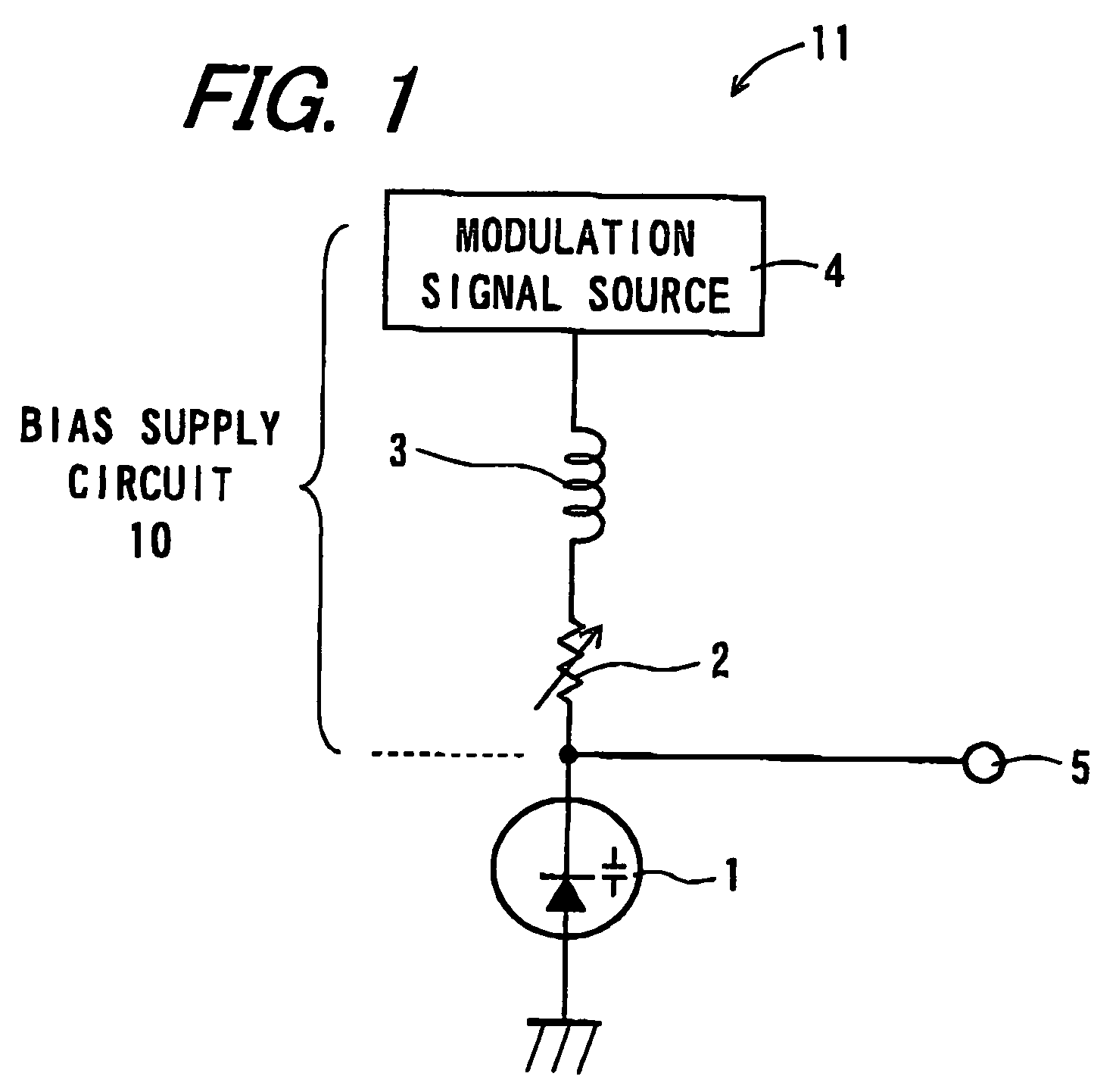
[0159] A high-frequency oscillator was configured by connecting a bias supply circuit 10 to a pill-type Gunn diode having the varactor diode 1 shown by a circuit diagram in FIG. 1 therein as shown by a circuit diagram in FIG. 1. First, as the trimmable chip resistor 2, a resistor such that the regulation range of the resistance value thereof was 1 to 10 kΩ (in this case, the initial value was 1 kΩ and the regulative maximum value was 10 kΩ) in which it was possible to obtain a desired frequency variable range was selected, a plurality of trimmable chip resistors 2 were subjected to trimming as shown in FIG. 4A, and controllability of the resistance value was checked. An example thereof is shown by a diagram in FIG. 14.

[0160]FIG. 14 is a diagram showing the relation between a number of times of trimming processes to the trimmable chip resistor 2 and a resistance value thereof in the example of the high-frequency oscillator 11 of the invention, with a number of times N (unit: times) ...


PUM


Abstract

A high-frequency oscillator that can tune oscillation characteristics is provided. A high-frequency oscillator includes a Gunn diode serving as a high-frequency oscillation element that generates high-frequency signals, a resonator connected to the Gunn diode, a varactor diode serving as a variable-capacitance element that is disposed on the resonator and changes a resonance frequency, and a bias supply circuit that is connected to the varactor diode and supplies a bias voltage applied in order to change a capacitance. The bias supply circuit includes a trimmable chip resistor serving as a pre-set variable resistor that regulates a bias voltage applied to the varactor diode. By regulating the resistance value of the trimmable chip resistor, it is possible to control the capacitance value of the varactor diode and tune oscillation characteristics to a desired state.

Description

BACKGROUND OF THE INVENTION [0001] 1. Field of the Invention [0002] The present invention relates to a high-frequency oscillator for use in a millimeter-wave integrated circuit, a millimeter-wave radar module or the like, and specifically, to a high-frequency oscillator in which a bias supply circuit of a variable-capacitance element as a component of the high-frequency oscillator is provided with a pre-set variable resistor, and which can tune oscillation characteristics such as an oscillation frequency and a frequency modulation width to a desired state with the pre-set variable resistor, and to a high-frequency transmission-reception apparatus using the high-frequency oscillator. [0003] Further, the invention relates to a radar apparatus comprising the aforementioned high-frequency transmission-reception apparatus, and to a radar-apparatus-equipped vehicle and a radar-apparatus-equipped small boat that are equipped with the radar apparatus. [0004] 2. Description of the Related Ar...

Claims


Application Information

Patent Timeline
Patent Type & Authority Applications(United States)
IPC IPC(8): G01S13/93G01S13/08G01S7/28
CPCG01S7/032G01S7/034G01S7/35H03D9/0641G01S2013/9371H03B19/14G01S7/4004G01S2013/9327
Inventor HAYATA, KAZUKIKISHIDA, YUJI
Owner KYOCERA CORP
Why Eureka
Try Eureka