
Chlorine dioxide solution generator with temperature control capability

a technology of chlorine dioxide and generator, which is applied in the direction of combustible gas purification/modification, lighting and heating apparatus, and separation processes, etc. it can solve the problems of chlorinated organic compounds, chlorinated organic compounds are suspected to increase cancer risk, and closub>2 /sub>is unstable in the gas phase, and is easy to decompos

Inactive Publication Date: 2006-02-02
PURELINE TREATMENT SYST
View PDF9 Cites 15 Cited by
  • Summary
  • Abstract
  • Description
  • Claims
  • Application Information

AI Technical Summary

Benefits of technology

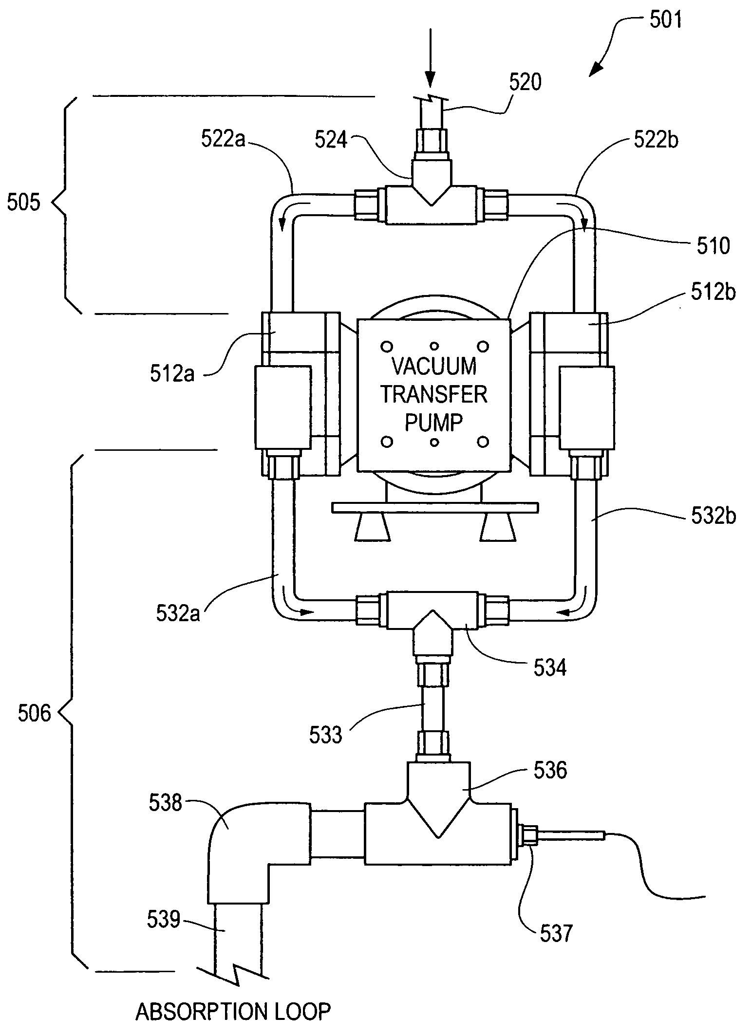
[0017] (2) an exhaust manifold assembly extending from the at least one gas transfer pump outlet port. The exhaust manifold assembly comprises at least one manifold conduit defining an interior volume for directing the pressurized ClO2 gas stream from the at least one gas transfer pump outlet port to the absorption loop. The at least one manifold conduit interior volume is sufficiently large to inhibit ClO2 decomposition in the pressurized ClO2 gas stream.
[0019] In a preferred chlorine dioxide solution generator, the gas transfer pump has first and second inlet ports for receiving first and second ClO2 gas streams from the ClO2 gas source. The gas transfer pump has first and second outlet ports for discharging first and second pressurized ClO2 gas streams. The discharge manifold assembly comprises first and second manifold conduits defining an aggregate conduit interior volume for directing the first and second pressurized ClO2 gas streams, respectively, from the gas transfer pump to the absorption loop. The aggregate manifold conduit interior volume is sufficiently large to inhibit ClO2 decomposition in the pressurized ClO2 gas stream.

Problems solved by technology

The use of chlorine, on the other hand, can result in the creation of chlorinated organic compounds when treating water.
Such chlorinated organic compounds are suspected to increase cancer risk.
ClO2 is, however, unstable in the gas phase and will readily undergo decomposition into chlorine gas (C12), oxygen gas (O2), and heat.
Moreover, in reactor-based chemical methods, the use of concentrated acids and chlorine gas poses a safety concern.
An operational problem can occur, however, when air is simultaneously introduced into a water system while educing the ClO2 gas.
A significant corrosion potential results from oxygen in air being added into the system.
Another problem can occur when introducing ClO2 gas into a pressurized water system.
Treating water in pressurized systems can be difficult when using educed ClO2 gas, since high-pressure booster pumps may be needed along with high-performance eductors.
This not only increases cost, but also raises maintenance concerns, since high-performance eduction systems can be unreliable as operating pressures near or above 30 to 50 pounds per square inch (psi) (206.8 to 344.7 kilopascal (kPa)).
The foregoing eductor-based method is less effective, however, in systems in which a ClO2 stream is directed against a head pressure.
It is known that ClO2 is unstable and capable of decomposing, in which ClO2 undergoes an exothermic reaction to form chlorine and oxygen.
(73° C.) can result in potentially hazardous and less efficient operation of the generator.
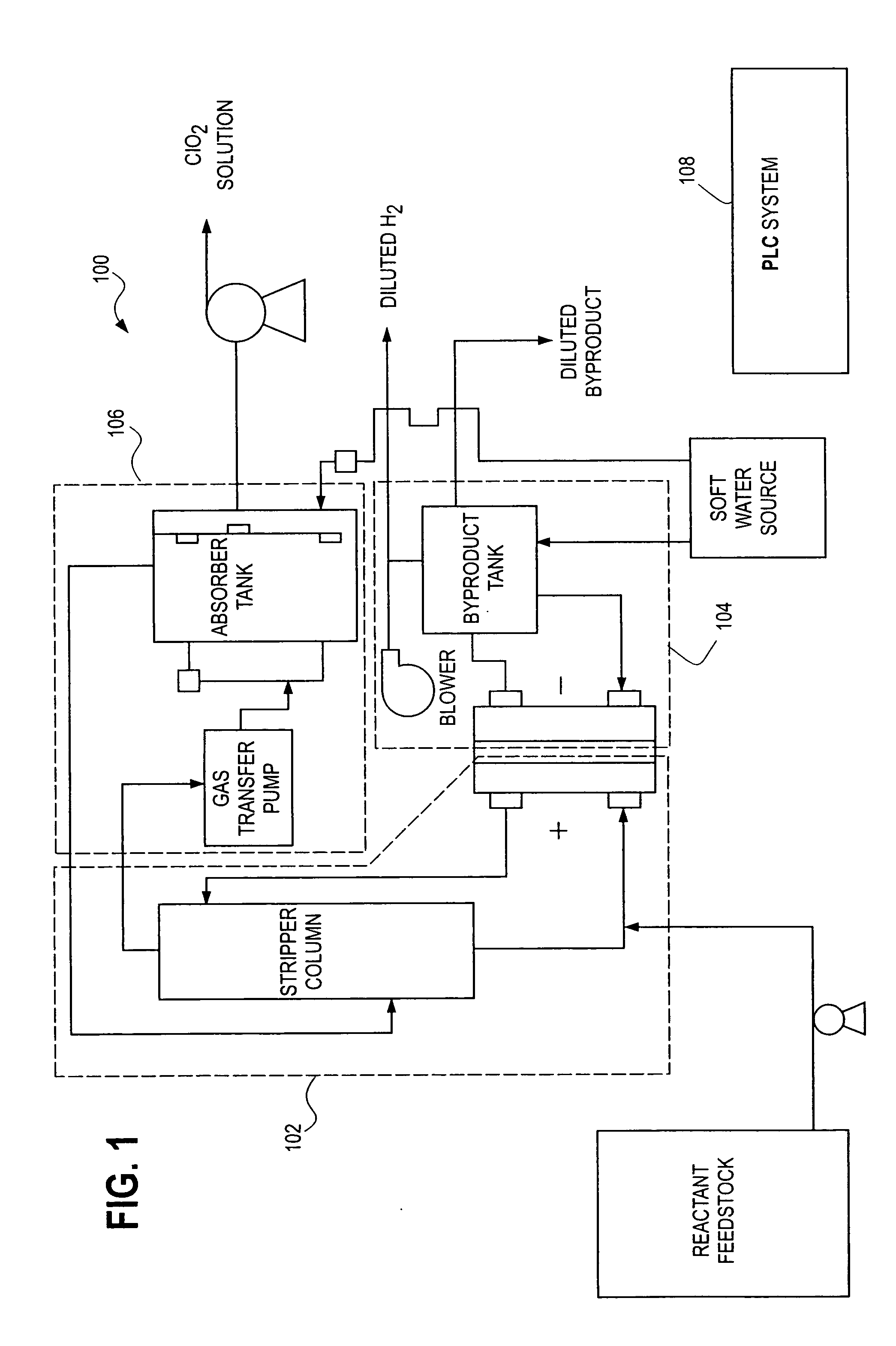
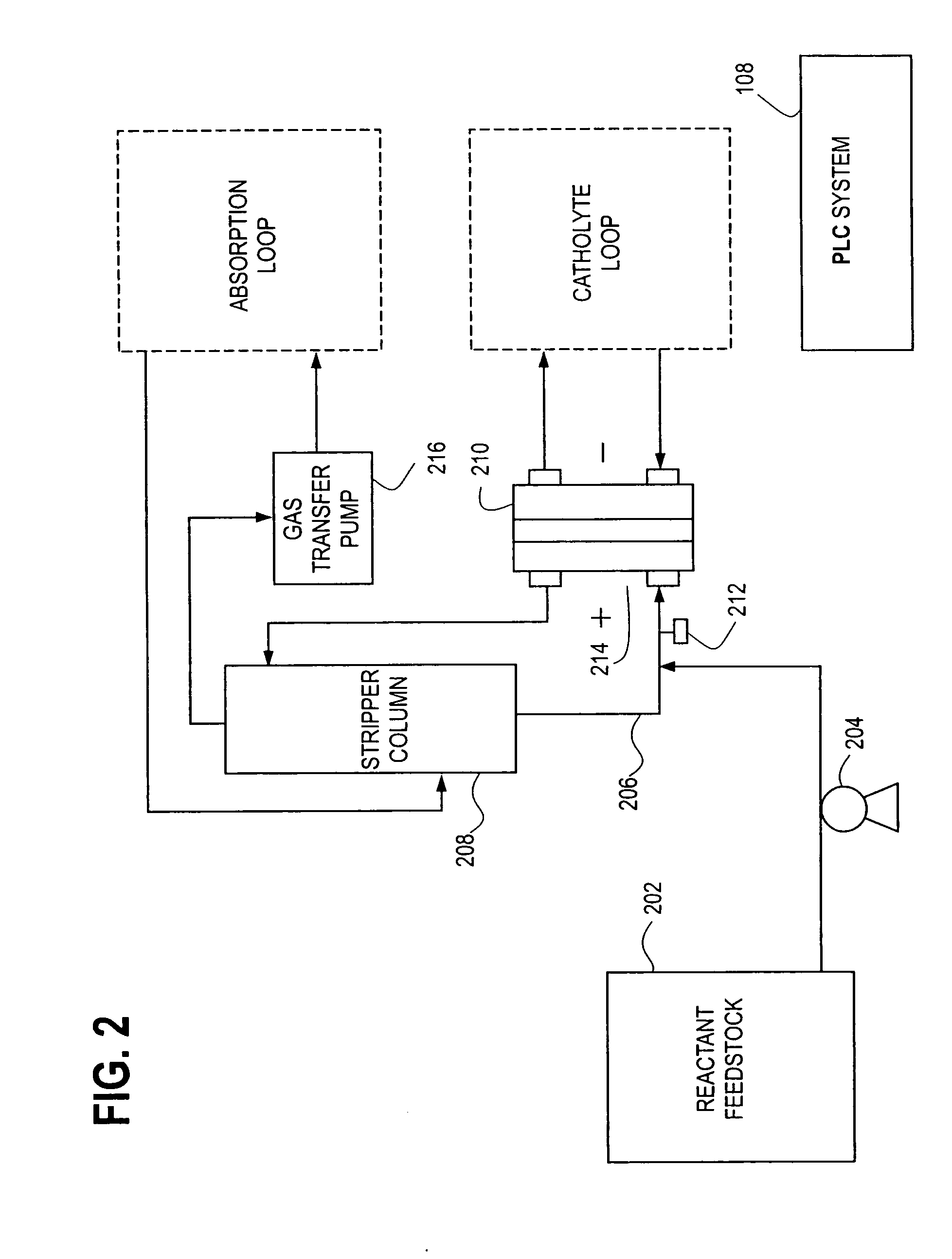
In the present technique, in which the ClO2 solution generator has temperature control capability, the operating temperature can be reduced and maintained below the level at which the exothermic reaction to form chlorine and oxygen causes the ClO2 generation process to become hazardous and less efficient.

Method used


Image

  • Chlorine dioxide solution generator with temperature control capability
  • Chlorine dioxide solution generator with temperature control capability
  • Chlorine dioxide solution generator with temperature control capability

Examples


example 1

[0067] The ClO2 gas stream exiting the pump orifice in FIGS. 5a, 5b and 5c, which has a diameter of 0.25 inch (0.64 cm) can be cooled by expanding the volume of the gas stream. The extent of expansion should be such that the induction period for decomposition of ClO2 at the temperature and pressure indicated is greater than 20 seconds. According to published graphs in the technical literature (see, for example, Loss Prevention Bulletin, I. Chem. E. 113, October 1993 by G. Cowley), the temperature and induction period for 5 percent by volume of ClO2 in air (corresponds to a partial pressure of 38 mm of Hg) shown in Table 1 below.

TABLE 1Induction period to decomposition of ClO2 (5% byvolume in air) at a partial pressure of 38 mm HgTemperatureInduction Period(° F. / ° C.)(minutes)163 / 730.33124 / 5160106 / 41400

[0068] In the present chlorine dioxide solution generator with temperature control capability, the ClO2 temperature is preferably reduced to and maintained at below 163° F. (73° C.)....


PUM

PropertyMeasurementUnit
Temperatureaaaaaaaaaa
Melting pointaaaaaaaaaa
Lengthaaaaaaaaaa

Abstract

A chlorine dioxide solution generator includes a chlorine dioxide gas source and an absorption loop for effecting the dissolution of chlorine dioxide into a liquid stream. A gas transfer assembly is interposed between the chlorine dioxide gas source and the absorption loop. The gas transfer assembly includes a gas transfer pump and an exhaust manifold assembly. The exhaust manifold assembly includes a manifold conduit defining an interior volume for directing the pressurized chlorine dioxide gas stream from the pump outlet to the absorption loop. The manifold conduit interior volume is sufficiently large to inhibit chlorine dioxide decomposition in the pressurized chlorine dioxide gas stream by induce a pressurized chlorine dioxide gas stream temperature within the manifold conduit of less than about 163° F. (73° C.).

Description

CROSS-REFERENCE TO RELATED APPLICATION(S) [0001] This application is a continuation-in-part of U.S. patent application Ser. No. 10 / 902,681 filed on Jul. 29, 2004, entitled “Chlorine Dioxide Solution Generator”. The '681 application is hereby incorporated by reference herein in its entirety.FIELD OF THE INVENTION [0002] The present invention relates generally to chlorine dioxide generators and to the use of such generators in water treatment systems. More particularly, the present invention relates to a chlorine dioxide generator for producing a chlorine dioxide solution, in which the temperature of the chlorine dioxide stream is controlled to reduce or avoid decomposition of chlorine dioxide in the stream. BACKGROUND OF THE INVENTION [0003] Chlorine dioxide (ClO2) has many industrial and municipal uses. When produced and handled properly, ClO2 is an effective and powerful biocide, disinfectant and oxidizer. [0004] ClO2 is also used extensively in the pulp and paper industry as a ble...

Claims


Application Information

Patent Timeline
IPC IPC(8): B01F3/04
CPCC01B11/024C02F2301/046C02F2209/02C02F1/4674C01B11/023C02F1/763C25B1/26
Inventor NANJUNDIAH, CHENNIAHHAWN, LARRY L.DOTSON, JEFFREY M.
Owner PURELINE TREATMENT SYST
Learn More