
Firing furnace, porous ceramic member manufacturing method using the same, and porous ceramic member manufactured by the manufacturing method

a manufacturing method and technology of porous ceramics, applied in muffle furnaces, furnaces, lighting and heating apparatuses, etc., can solve the problems of reducing heat insulating performance, warping tends to occur corrosion in the heat insulating layer,

Active Publication Date: 2006-02-09
IBIDEN CO LTD
View PDF79 Cites 149 Cited by
  • Summary
  • Abstract
  • Description
  • Claims
  • Application Information

AI Technical Summary

Benefits of technology

[0056] In the firing furnace having the above-mentioned structure, upon manufacturing porous ceramic members such as oxide ceramics, carbide ceramics other than silicon carbide, nitride ceramics and the like, it is also possible to prevent the warping of the heat insulating layer due to changes in physical properties such as thermal expansion coefficient and the like.
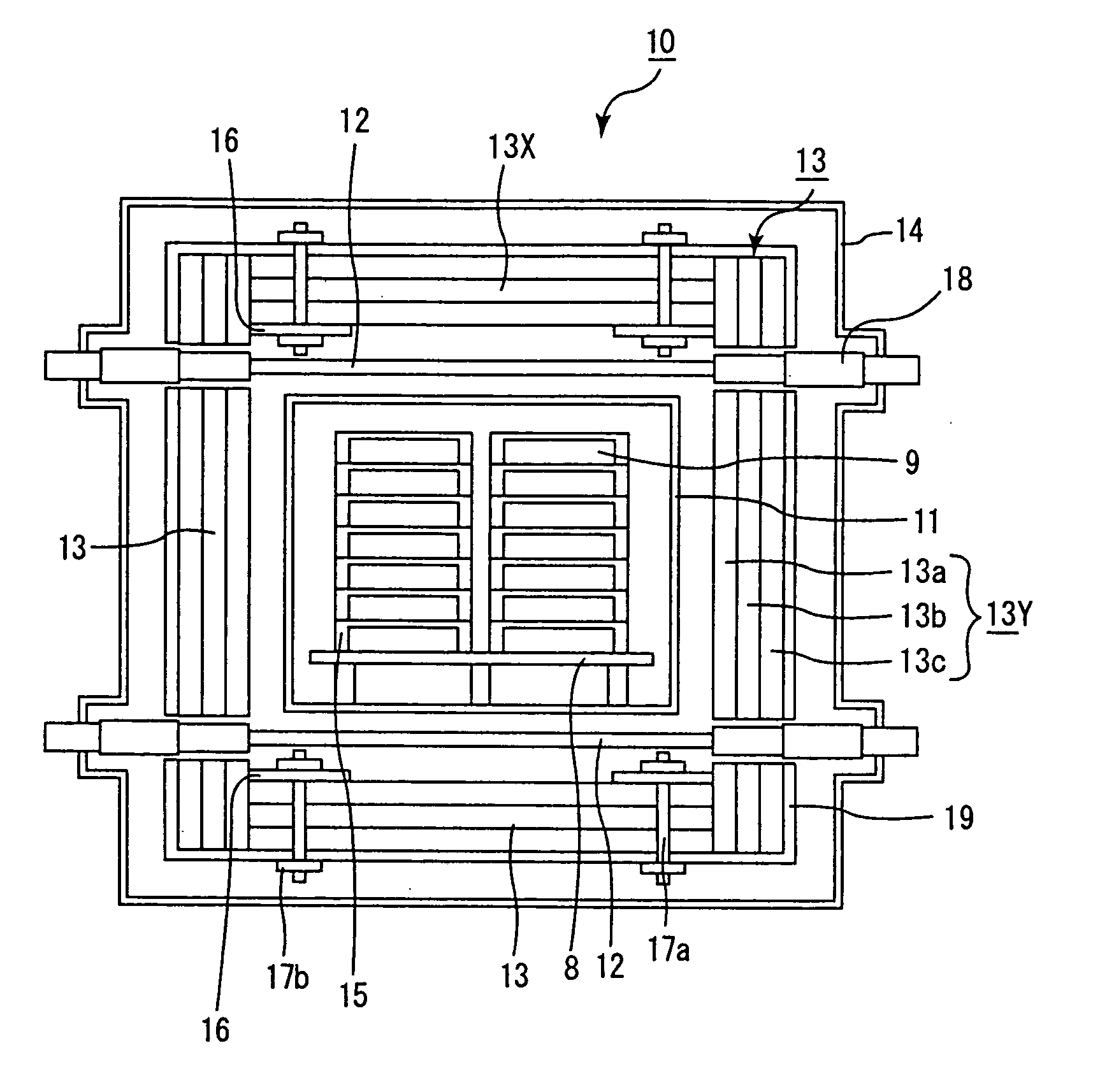
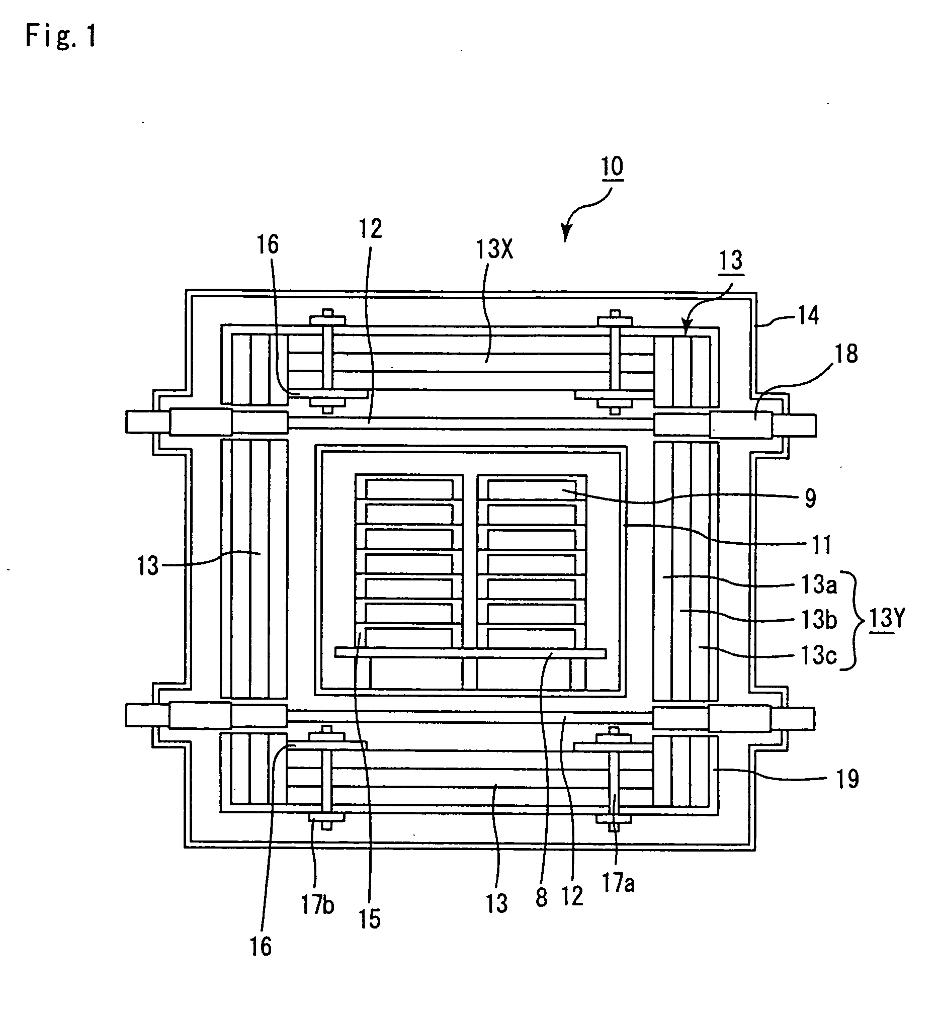
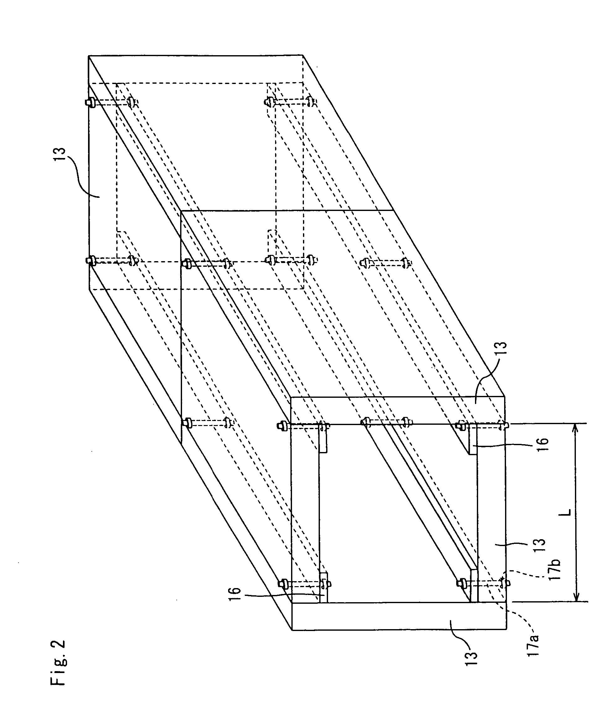
[0018] A second aspect of the present invention is related to a firing furnace comprising: a muffle formed so as to ensure a space for housing a formed body to be fired; a member that constitutes a heat generator and is placed on and / or around the muffle; and a heat insulating layer that contains the muffle and the heat generator inside thereof. Herein, the heat insulating layer is secured to a heat insulating layer attaching-enclosing member that is located on the periphery of the heat insulating layer by using a combining member.
[0020] A third aspect of the present invention is related to a firing furnace comprising: a muffle formed so as to ensure a space for housing a formed body to be fired; a member that constitutes a heat generator and is placed on and / or around the muffle; and a heat insulating layer that contains the muffle and the heat generator inside thereof. Herein, the heat insulating layer is divided into a plurality of heat insulating layers, while a reinforcing member that combines and reinforces the divided insulating layers arranged therein.
[0023] A fourth aspect of the present invention is related to a porous ceramic member manufacturing method, upon firing a formed body to form a porous ceramic member, said method using a firing furnace that comprises: a muffle formed so as to ensure a space for housing the formed body to be fired; a member that constitutes a heat generator and is placed on and / or around the muffle; and a heat insulating layer that contains the muffle and the heat generator inside thereof. Herein, a carbon-natured sheet is placed in the vicinity of corner portions of an inner face of the heat insulating layer.
[0009] The firing furnace to be used for manufacturing such non-oxide ceramic members is provided with a heater and the like in the furnace and a heat insulating layer mainly made of carbon.
[0056] In the firing furnace having the above-mentioned structure, upon manufacturing porous ceramic members such as oxide ceramics, carbide ceramics other than silicon carbide, nitride ceramics and the like, it is also possible to prevent the warping of the heat insulating layer due to changes in physical properties such as thermal expansion coefficient and the like.
[0028] A sixth aspect of the present invention is related to a porous ceramic member manufacturing method, upon firing a formed body to form a porous ceramic member, said method using a firing furnace that comprises: a muffle formed so as to ensure a space for housing the formed body to be fired; a member that constitutes a heat generator and is placed on and / or around the muffle and a heat insulating layer that contains the muffle and the heat generator inside thereof. Herein, the heat insulating layer is divided into a plurality of heat insulating layers, while a reinforcing member that combines and reinforces the divided insulating layers is arranged therein.

Problems solved by technology

Thus, warping tends to occur in the heat insulating layer.
Moreover, in combination with the conversion into silicon carbide and the like, reaction of carbon with oxygen remaining inside the furnace or with oxygen and the like generated from the formed body causes corrosion in the heat insulating layer.
When warping and corrosion occur in the heat insulating layer, the heat insulating performance is lowered, or separation or the like occurs in the heat insulating layer, making the firing furnace unable to function as a furnace; consequently, the heat insulating layer needs to be exchanged.
However, changing the heat insulating layer requires high costs, resulting in a problem of high manufacturing costs.
Moreover, even if the heat insulating layer does not need to be changed, an efficient heating process is no longer available and firing costs increase when the heat insulating property of the firing furnace is deteriorated.

Method used


Image

  • Firing furnace, porous ceramic member manufacturing method using the same, and porous ceramic member manufactured by the manufacturing method
  • Firing furnace, porous ceramic member manufacturing method using the same, and porous ceramic member manufactured by the manufacturing method
  • Firing furnace, porous ceramic member manufacturing method using the same, and porous ceramic member manufactured by the manufacturing method

Examples


example 1

[0158] (1) Powders of α-type silicon carbide having an average particle diameter of 10 μm (60% by weight) and powders of α-type silicon carbide having an average particle diameter of 0.5 μm (40% by weight) were wet-mixed, and to 100 parts by weight of the resulting mixture were added and kneaded 5 parts by weight of an organic binder (methyl cellulose) and 10 parts by weight of water to obtain a mixed composition. Next, after a slight amount of a plasticizer and a lubricant had been added and kneaded therein, the resulting mixture was extrusion-formed to form a raw formed product.

[0159] Next, after the above-mentioned raw formed product had been dried by using a microwave drier or the like to form a ceramic dried body, predetermined through holes were filled with a paste having the same composition as the raw formed product. After having been again dried by using a drier, the resulting product was degreased at 400° C., and fired at 2200° C. in a normal-pressure argon atmosphere for...

example 2

[0164] The same processes as Example 1 were carried out except that DON-3000 (graphite foil, made by Donack Co., Ltd., density: 0.15 g / cm3) was used as the carbon-natured sheets to be placed on end portions of the inner face of upper and lower heat insulating layers that constitute the firing furnace to manufacture porous ceramic members, and the resulting porous ceramic members were used to manufacture a honeycomb structural body. In this case, the processes used for manufacturing the porous ceramic members were continuously repeated for 1000 hours in the same manner as Example 1, and the heat insulating layers constituting the firing furnace were observed for any warping.

[0165] As a result, no warping was observed in the same manner as Example 1.

[0166] The honeycomb structural body in which the porous ceramic members thus manufactured were used was able to sufficiently satisfy properties as a filter, and the honeycomb structural body, which was manufactured by using porous ceram...

example 3

[0167] The same processes as Example 1 were carried out except that no carbon-natured sheets were placed on end portions of the inner face of upper and lower heat insulating layers that constitute the firing furnace, with the heat insulating layers 13 being secured to a heat insulating layer attaching-enclosing member 19 with bolts 17a and nuts 17b serving as combining members, to manufacture porous ceramic members and a honeycomb structural body formed thereby.

[0168] In this case, the process used for manufacturing the porous ceramic members were continuously carried out for 1000 hours in the same manner as Example 1, and after a lapse of 700 hours as well as after a lapse of 1000 hours, the heat insulating layers forming the firing furnace were observed for any warping. As a result, no warping was observed in the heat insulating layers in any of the lapses of time.

[0169] The honeycomb structural body in which the porous ceramic members thus manufactured were used was able to suf...


PUM

PropertyMeasurementUnit
temperatureaaaaaaaaaa
lengthaaaaaaaaaa
densityaaaaaaaaaa

Abstract

A firing furnace comprising: a muffle formed so as to ensure a space for housing a formed body to be fired; a member that constitutes a heat generator and is placed on and / or around the muffle; and a heat insulating layer that contains said muffle and said heat generator inside thereof, wherein a carbon-natured sheet is placed in the vicinity of corner portions of an inner face of said heat insulating layer.

Description

CROSS-REFERENCE TO RELATED APPLICATIONS [0001] This application claims benefit of priority to Japanese Patent Application No. 2004-228649, filed on Aug. 4, 2004, PCT Application No. PCT / JP2005 / 001264, filed on Jan. 28, 2005, and PCT Application No. PCT / JP2005 / 002073, filed on Feb. 10, 2005. [0002] The contents of those Applications are incorporated herein by reference in their entirety. BACKGROUND OF THE INVENTION [0003] 1. Field of the Invention [0004] The present invention relates to: a firing furnace that is used for manufacturing a honeycomb structural body made of ceramics, a ceramic material and the like; a porous ceramic member manufacturing method using the same; and a porous ceramic member manufactured by the manufacturing method. [0005] 2. Discussion of the Background [0006] There have been proposed various exhaust gas purifying honeycomb filters and catalyst supporting members which are used for purifying exhaust gases discharged from internal combustion engines of vehicl...

Claims


Application Information

Patent Timeline
Patent Type & Authority Applications(United States)
IPC IPC(8): F27D1/00
CPCF27B5/04F27B5/08F27B5/10F27B5/14F27D2099/0015F27B9/067F27D1/0006F27D99/0006F27B9/063Y02P10/25F27B9/32F27B9/06F27B5/06C04B35/64
Inventor SAIJO, TAKAMITSUHIROSHIMA, YUICHIKOYAMA, TATSUYA
Owner IBIDEN CO LTD
Learn More