
Acoustic wave sensor with reduced condensation and recovery time

a technology of acoustic waves and sensors, applied in the field of sensors, systems, can solve the problems of repeated heating, loss of memory of previously learned odors, irreversible change of polyimide films, etc., and achieve the effect of lessening the damping of them

Inactive Publication Date: 2006-02-16
HONEYWELL INT INC
View PDF26 Cites 35 Cited by
  • Summary
  • Abstract
  • Description
  • Claims
  • Application Information

AI Technical Summary

Benefits of technology

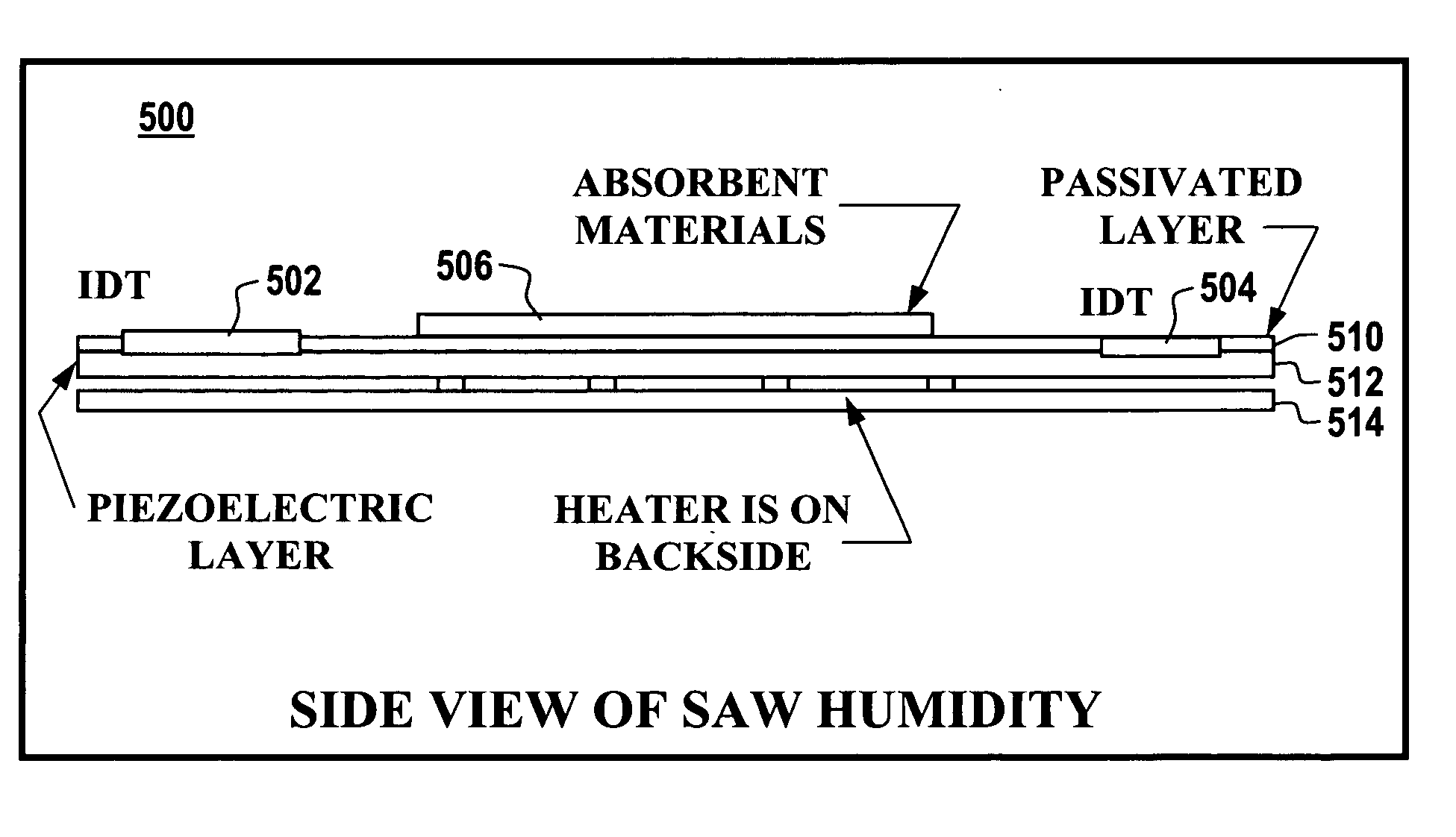
[0022] The plurality of acoustic waves propagating across the surface of the piezoelectric substrate comprise multiple mode frequency outputs, wherein at least one frequency mode thereof can be optimized while all remaining frequency modes among the multiple mode frequency outputs are suppressed in order to generate particular data indicative of a monitored chemical species (e.g., humidity). The piezoelectric substrate can vibrate in the optimized frequency mode when condensation occurs in a vicinity of the piezoelectric substrate, such the condensation acts as a damping force thereon. The piezoelectric substrate generally vibrates in a shear horizontal direction in order to lessen damping thereof.

Problems solved by technology

Because of their relatively short lifetimes, such sensors are replaced more often than those based on metal oxide.
When sensors are replaced, they lose their memory of previously learned odors.
One of the disadvantages with polymers, however, such as a polyimide film used in most humidity sensors, is that repeated heating can delaminate the polymer or polyimide film due to thermal expansion coefficient mismatch with the substrate and absorption in general.
Heating therefore can cause irreversible change to the polyimide film.
In high condensing applications (e.g., a fuel cell), a sensor that relies upon a polymer or polyimide film cannot meet these requirements.

Method used


Image

  • Acoustic wave sensor with reduced condensation and recovery time
  • Acoustic wave sensor with reduced condensation and recovery time
  • Acoustic wave sensor with reduced condensation and recovery time

Examples


Embodiment Construction

[0034] The particular values and configurations discussed in these non-limiting examples can be varied and are cited merely to illustrate at least one embodiment and are not intended to limit the scope of the invention.

[0035] Many modes of vibrations can exist in an acoustic wave device. Acoustic wave devices are typically designed such that only one mode of vibration is optimized, while other modes are suppressed. Such “undesired” mode(s), however, can be utilized for desorption in affinity / adsorption type sensors. Such modes can include, for example, flexural plate mode (FPM), acoustic plate mode, shear-horizontal acoustic plate mode (SH-APM), amplitude plate mode (APM), thickness shear mode (TSM), surface acoustic wave mode (SAW), bulk acoustic wave mode (BAW), Torsional mode, love wave, leaky surface acoustic wave mode (LSAW), pseudo surface acoustic wave mode (PSAW), transverse mode, surface-skimming mode, surface transverse mode, harmonic modes, and / or overtone modes. Thus, i...


PUM


Abstract

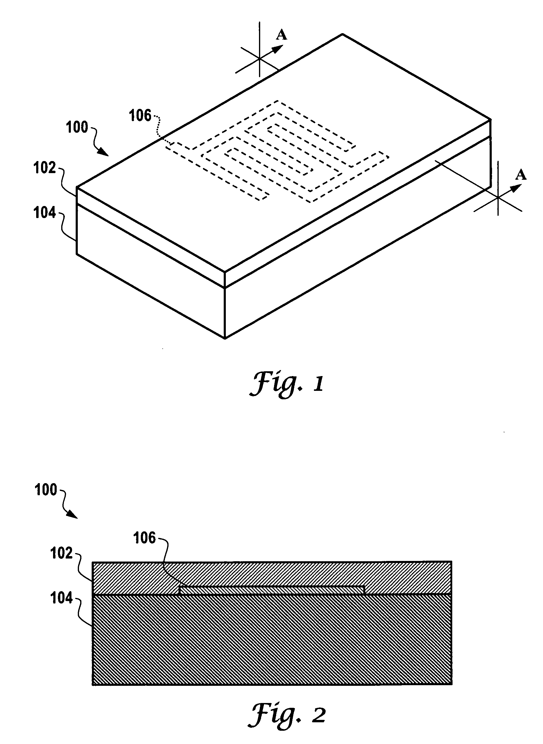
An acoustic wave sensor apparatus is disclosed, which generally includes a piezoelectric substrate having a surface thereon. One or more interdigital transducers and a passivation layer can be formed upon the piezoelectric substrate. Additionally, an absorbent material can be formed upon the acoustic path (IDTs, electrodes, etc), such that the interdigital transducers respond to a plurality of acoustic waves propagating across the surface of the piezoelectric substrate, thereby providing data indicative of humidity in the vicinity of the piezoelectric substrate, along with the passivation layer and the interdigital transducers. Additionally, one or more heaters can be formed upon a side of the piezoelectric substrate opposite the side of the piezoelectric substrate upon which the interdigital transducers, the passivation and the absorbent material are located. The heater can be preferably configured from a material such as platinum.

Description

TECHNICAL FIELD [0001] Embodiments are generally related to sensing devices, systems and methods. Embodiments are also related to acoustic wave sensors, such as, for example, surface acoustic wave (SAW) and bulk acoustic wave (BAW) devices and sensors. Embodiments are further related to humidity and condensation sensing applications. BACKGROUND OF THE INVENTION [0002] Acoustic wave sensors are utilized in a number of sensing applications, such as, for example, temperature, pressure, humidity and / or gas sensing devices and systems. Examples of acoustic wave sensors include devices such as acoustic wave sensors, which can be utilized to detect the presence of substances, such as chemicals and biological materials. An acoustic wave (e.g., SAW / BAW) device acting as a sensor can provide a highly sensitive detection mechanism due to the high sensitivity to surface loading and the low noise, which results from their intrinsic high Q factor. [0003] Surface acoustic wave devices are typicall...

Claims


Application Information

Patent Timeline
IPC IPC(8): G01N19/10
CPCG01N29/022G01N29/2462G01N29/326G01N2291/0427G01N2291/02845G01N2291/0422G01N2291/0423G01N2291/0256
Inventor LIU, JAMES Z.
Owner HONEYWELL INT INC
Learn More