Joining apparatus and method

a technology of joining apparatus and joining method, which is applied in the direction of soldering apparatus, manufacturing tools,auxillary welding devices, etc., can solve the problems of inability to effectively remove joining inhibitors, complex structure, and indispensible structure related to the cleaning process of electrodes, so as to achieve effective removal of joining inhibitors, improve the quality of simplify the structure related to the cleaning process of objects

Inactive Publication Date: 2006-02-23
PANASONIC CORP
View PDF23 Cites 19 Cited by
  • Summary
  • Abstract
  • Description
  • Claims
  • Application Information

AI Technical Summary

Benefits of technology

[0061] According to the present invention, the structure related to the cleaning process of objects can be simplified so that the metal joining can simply be fulfilled. Further, before execution of metal joining, ultraviolet ray is applied to the surfaces of metallic portions in the respective objects to remove joining inhibitors, with the result that clean surfaces are exposed, and thereafter, the two metallic portions are brought into contact with each other to achieve the metal joining. Thus, the resultant joining strength can be improved. Besides, by using ultraviolet ray within the wavelength range of 160 nm to 180 nm as the ultraviolet ray to be used for cleaning process, it becomes possible to effectively achieve the removal of joining inhibitors.
[0062] Further, even with ob

Problems solved by technology

As a result of this, the structure related to the cleaning process of electrodes indispensably becomes one which is an expensive, complex structure, including a chamber which defines a processing space for use of plasma processing, a mechanism which generates the plasma, and the like.
This poses a problem that the

Method used


Image

  • Joining apparatus and method
  • Joining apparatus and method
  • Joining apparatus and method

Examples


first embodiment

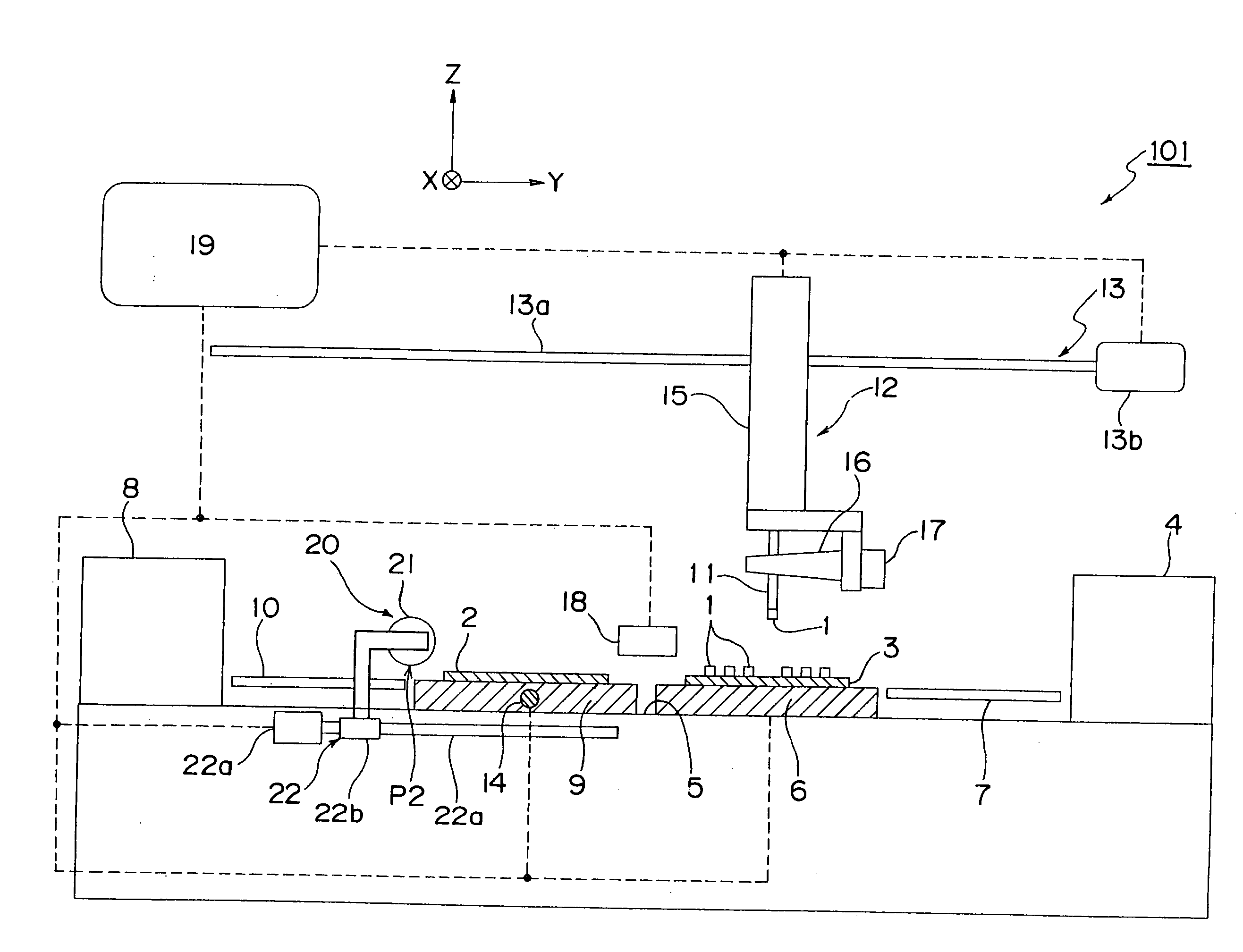
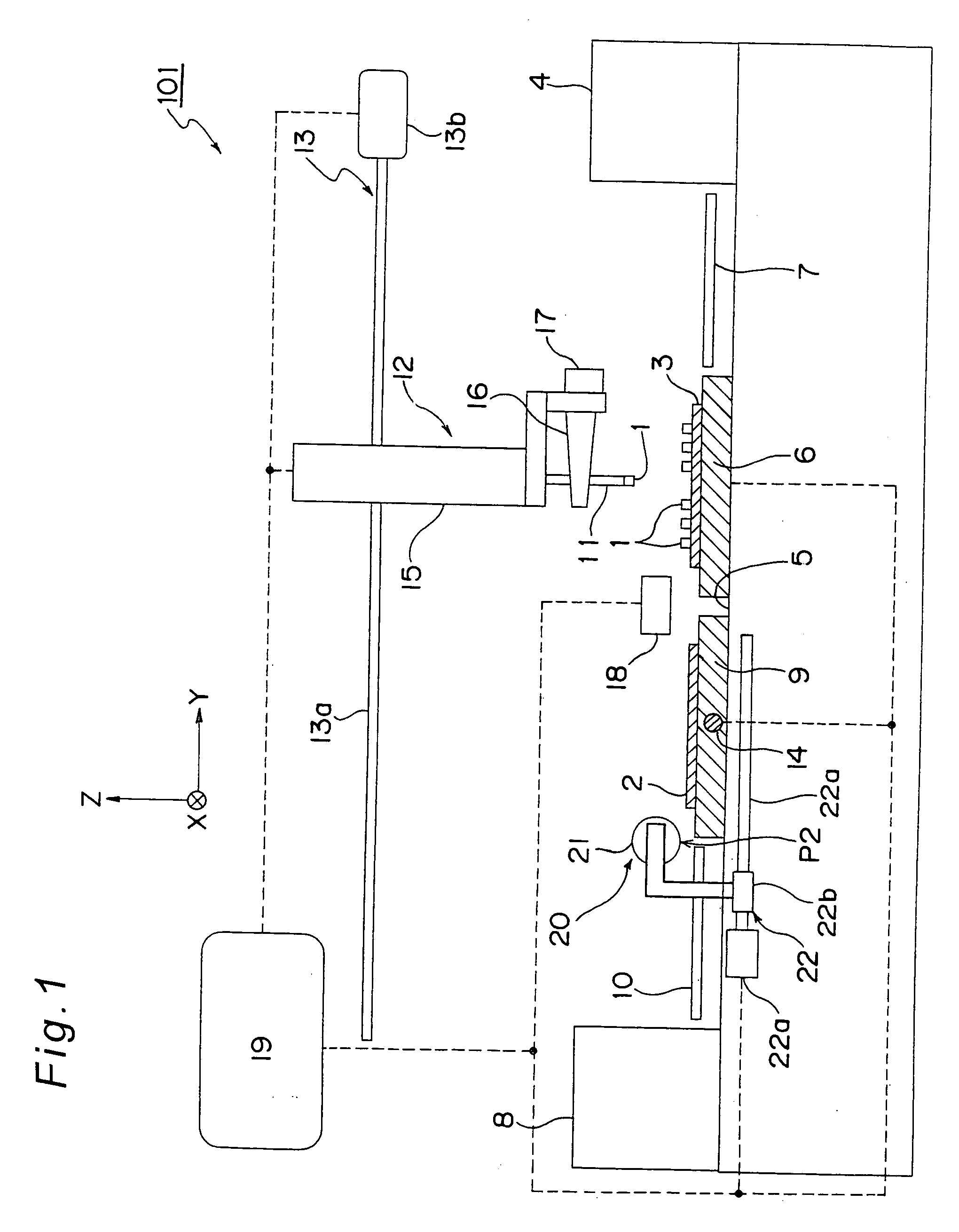
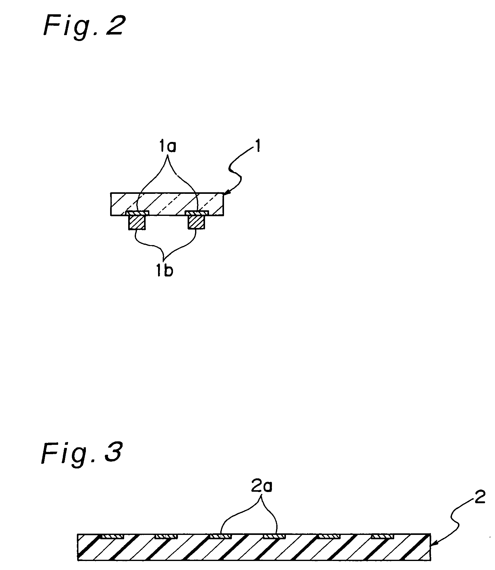
[0102]FIG. 1 is a schematic structural view of a joining apparatus 101 which is an example of the joining apparatus according to a first embodiment of the invention. The joining apparatus 101 is an apparatus for joining an electronic component 1, which is an example of a first object, to a specified position of a circuit board 2, which is an example of a second object, so that the electronic component 1 is mounted onto the circuit board 2.

[0103] As shown in FIG. 1, the joining apparatus 101 includes a component magazine 4 for housing therein a plurality of component trays 3 on each of which a plurality of electronic components 1 are feedably set, and a tray conveyance unit 7 for conveying a component tray 3, which has selectively been taken out from the component magazine 4, so as to be set on a component feed stage 6 placed on an apparatus frame 5. The joining apparatus 101 also includes a board magazine 8 for housing therein a plurality of circuit boards 2 to which each electroni...

modification example

[0131] The joining apparatus 101 of this first embodiment has been described on a case where the electronic component 1 is joined to the joining position of the circuit board 2 by metal joining after execution of the ultraviolet cleaning process. However, objects, of such joining are not limited to the electronic components 1 or the circuit boards 2. Instead of such a case, a case where a first container member as an example of the first object and a second container member as a second object are used is described below as a modification example of this first embodiment. It is noted that the joining method according to this modification example can be carried out in the above-described joining apparatus 101, and so the description of the structure of the joining apparatus is omitted.

[0132] First, in the joining apparatus 101, FIG. 13 shows a schematic explanatory view showing a state in which ultraviolet ray emitted from the excimer ultraviolet lamp 21 are being applied to the firs...

second embodiment

[0141] Next, FIG. 14 shows a schematic structural view showing a partial structure of a joining apparatus 201 which is an example of a joining apparatus according to a second embodiment of the present invention. This joining apparatus 201 is a device for performing joining and electrical connecting (i.e., mounting) of an electronic component 1 to a circuit board 2 as in the first embodiment. As shown in FIG. 14, in the joining apparatus 201, a heater 45 for heating the suction nozzle 11 is provided on a shaft 41 instead of the ultrasonic vibrator 17 and the horn 16 included in the joining apparatus 101 of FIG. 1. The other constituent members are the same as in the joining apparatus 101 of FIG. 1, and designated by the same reference numerals in the following description. In FIG. 14, the joining head 12 and the board stage 9 are depicted so as to be largely scaled down, compared with the other constituent members, as in FIG. 1. Also, the distances of the electronic component 1 and t...


PUM

PropertyMeasurementUnit
Fractionaaaaaaaaaa
Wavelengthaaaaaaaaaa
Pressureaaaaaaaaaa

Abstract

The joining apparatus includes a suction nozzle for holding an electronic component, a board stage for holding a circuit board in opposition to the electronic component, and an excimer ultraviolet lamp placed at an irradiation position between the positioned electronic component and circuit board. In such a joining apparatus, ultraviolet irradiation to Au bumps of the electronic component and ultraviolet irradiation to board electrodes of the circuit board are performed concurrently by the excimer ultraviolet lamp to execute cleaning process of the two metallic portions. Thereafter, ultrasonic vibrations are imparted to the two metallic portions while those metallic portions are kept in contact with each other, by which metal joining between the two metallic portions is fulfilled.

Description

TECHNICAL FIELD [0001] The present invention relates to a joining apparatus and a joining method for joining objects to each other. BACKGROUND OF THE INVENTION [0002] Conventionally, various joining methods have been used in apparatuses for joining objects to each other. As one of methods for joining objects having metallic portions to each other at comparatively low temperature, there has been known a method that the metallic portions are subjected to cleaning process such as removal of adsorbent substances, activation of surfaces or the like by applying plasma to the metallic portions before the metallic portions are joined each other. [0003] For example, Japanese unexamined patent publication No. 2001-60602 A proposes a technique that, in an apparatus for mounting electronic components onto circuit boards such as printed boards, an electrode of the circuit board is cleaned by applying plasma thereto, and thereafter joined to an electrode of the electronic component. Also, Japanes...

Claims


Application Information

Patent Timeline
IPC IPC(8): B23K31/02H05K3/26
CPCB23K20/10B23K2201/40H05K2203/0285H05K3/3489H05K3/328B23K2101/40H01L2224/75
Inventor HIGASHI, KAZUSHISASAOKA, TATSUOISHITANI, SHINJI
Owner PANASONIC CORP
Why Eureka
Try Eureka