
Method and device for producing a cutting or embossing roller by means of laser resurfacing welding

a laser resurfacing welding and cutting or embossing technology, which is applied in welding/cutting media/materials, metal working equipment, metal-working apparatus, etc., can solve the problems of high cost of cutting roller production, large wear, and significant stress on cutting or embossing projections, and achieve the effect of increasing power

Active Publication Date: 2006-03-02
WINKLER DUNNEBIER GMBH
View PDF14 Cites 22 Cited by
  • Summary
  • Abstract
  • Description
  • Claims
  • Application Information

AI Technical Summary

Benefits of technology

[0009] It is therefore an object of the present invention to provide a method and a device for producing a cutting or embossing roller, having a cutting knife or embossing projection that projects out of the surface of a base body of the roller, which guarantees the most optimal homogeneity of the cutting knife or the embossing projection that is possible, while simultaneously reducing the duration and costs of the production process.
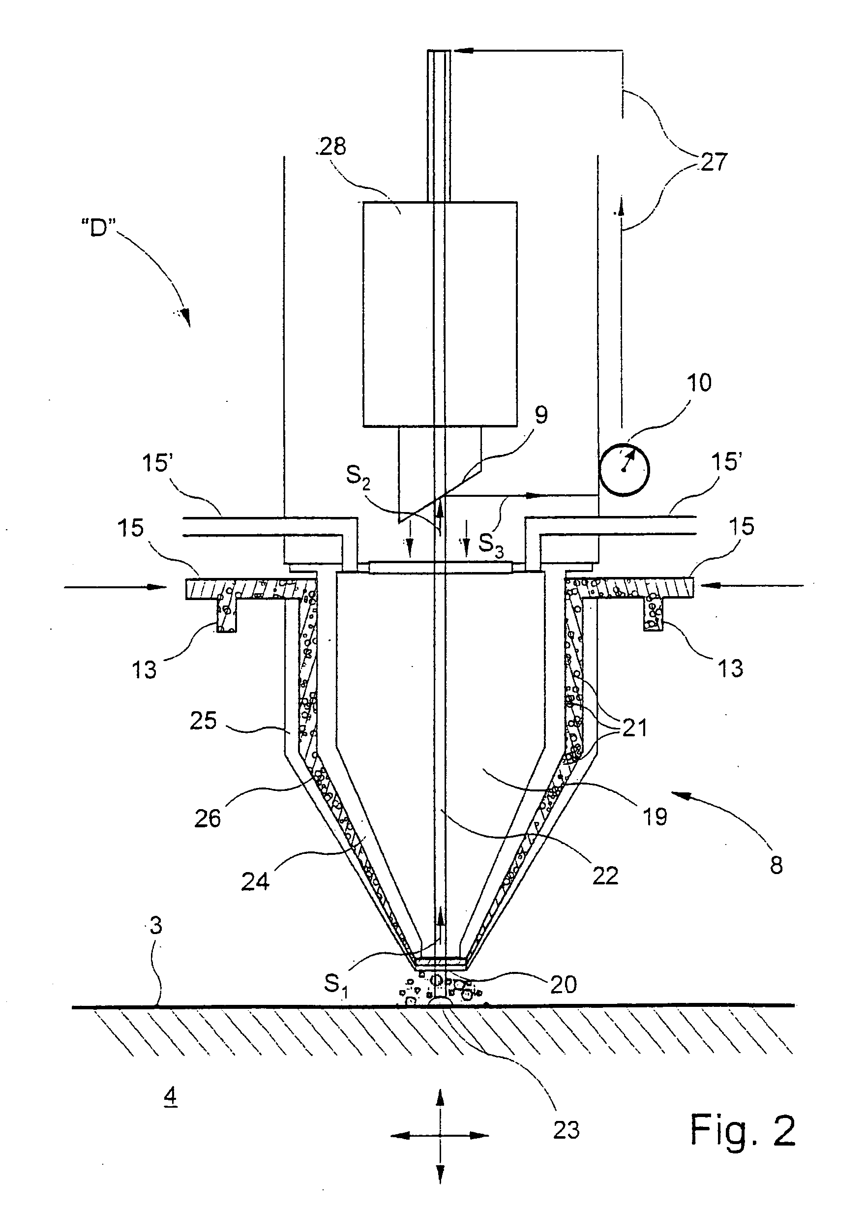
[0016] Since the temperature of the melt bath is essentially constant during the resurfacing welding process, uniform melting of the metallic powder used as the additional material always takes place. This uniform melting in turn results in the desired homogeneity of the cutting knife or embossing projection that is produced, so that the mechanical properties of the cutting knife or the embossing projection can be significantly improved. The heat and / or light radiation emitted by the melt bath is constantly being detected, at least during the resurfacing welding process, and the power of the laser is controlled or regulated as a function of this detection. As a result, the process according to the invention can react to temperature variations of the melt bath in real time. This ability results in a corresponding acceleration of the resurfacing welding process, since no significant cooling or heating times have to be taken into consideration.
[0018] Preferably, the laser resurfacing welding is carried out with a diode laser, particularly a low-energy diode laser. In this connection, the laser light generated using the diode laser preferably has a wavelength <1000 nm, particularly a superimposition of wavelengths from the range of 808 nm to 980 nm. A diode laser having a superimposition of the wavelengths of 940 nm and 980 nm yielded good welding results in the sense of the present invention. A low-energy diode laser furthermore has the advantage that the base material of the base body of the roller is heated only slightly, i.e. that a temperature of the base body of the roller of approximately 50 degrees or 60 degrees C. is not exceeded during the resurfacing welding. A diode laser that is suitable for the purposes of the present invention is, for example, the laser having the model name LDF 1000-2500 of the company Laserline GmbH in Mülheim-Kärlich.
[0019] The cross-section of the laser beam of a diode laser usually has an elliptical shape. This shape results in a direction dependence of the laser beam cross-section. This dependence does not allow welding of a cutting knife that has a rectangular shape in a top view, for example, with a uniform width. Preferably, the cross-section of the laser beam of the diode laser is therefore homogenized. For example, the cross-section is converted to a circular, direction-independent cross-section using a light guide fiber. Such a cross-section allows resurfacing welding of a cutting knife having any desired geometry in a top view, with a constant width of the weld seam.
[0021] In order to transport the additional material in powder form to the weld point, a pneumatic powder feed device is preferably provided. This device feeds the additional material in powder form to the working head from a supply container, using a transport gas. It is particularly advantageous to use such a gas composition for the transport gas that simultaneously functions as an inert gas, i.e. particularly prevents oxidation of the weld seam. By means of the selection of the composition of the transport gas, the waste heat stream from the weld point can furthermore be influenced. Alternatively, it is possible to arrange an inert gas feed device that is independent of and separate from the transport gas, in order to be able to select the composition of the transport gas independent of any inert gas function.
[0027] The device according to the invention, as a device for detecting the heat and / or light radiation emitted by the melt bath, preferably has an optical beam splitter and a measuring device for detecting a signal that corresponds to the temperature of the melt bath. In this connection, the beam splitter is disposed in the beam path of the laser light. A part of the radiation emitted by the melt bath returns to the working head and is deflected there, by the beam splitter of a measuring device, to detect a signal that corresponds to the temperature of the melt bath. This signal is finally passed to the control or regulation circuit of the laser. In this way, the power of the laser is throttled if a reference temperature is exceeded. The power is increased if the actual temperature is below the reference temperature. The energy level in the melt bath therefore remains essentially constant, so that the melting process of the additional material in powder form can run continuously.

Problems solved by technology

As a result, the cutting or embossing projections are exposed to significant stresses and subject to great wear.
The result was high costs in the production of the cutting rollers.
This welding method requires a relatively large amount of time for applying the weld seams to the base body of the roller.
This welding method also causes undesirable weld splashes on the surface of the base body of the roller, and not infrequently results in bubbles and / or cracks in the weld seams.
These bubbles or cracks reduce the ability of the cutting knives, which are subject to great stress, to withstand mechanical stress, and thereby reduce their useful lifetimes.
This requirement, of course, results in time delays in the production sequence.

Method used


Image

  • Method and device for producing a cutting or embossing roller by means of laser resurfacing welding
  • Method and device for producing a cutting or embossing roller by means of laser resurfacing welding
  • Method and device for producing a cutting or embossing roller by means of laser resurfacing welding

Examples


Embodiment Construction

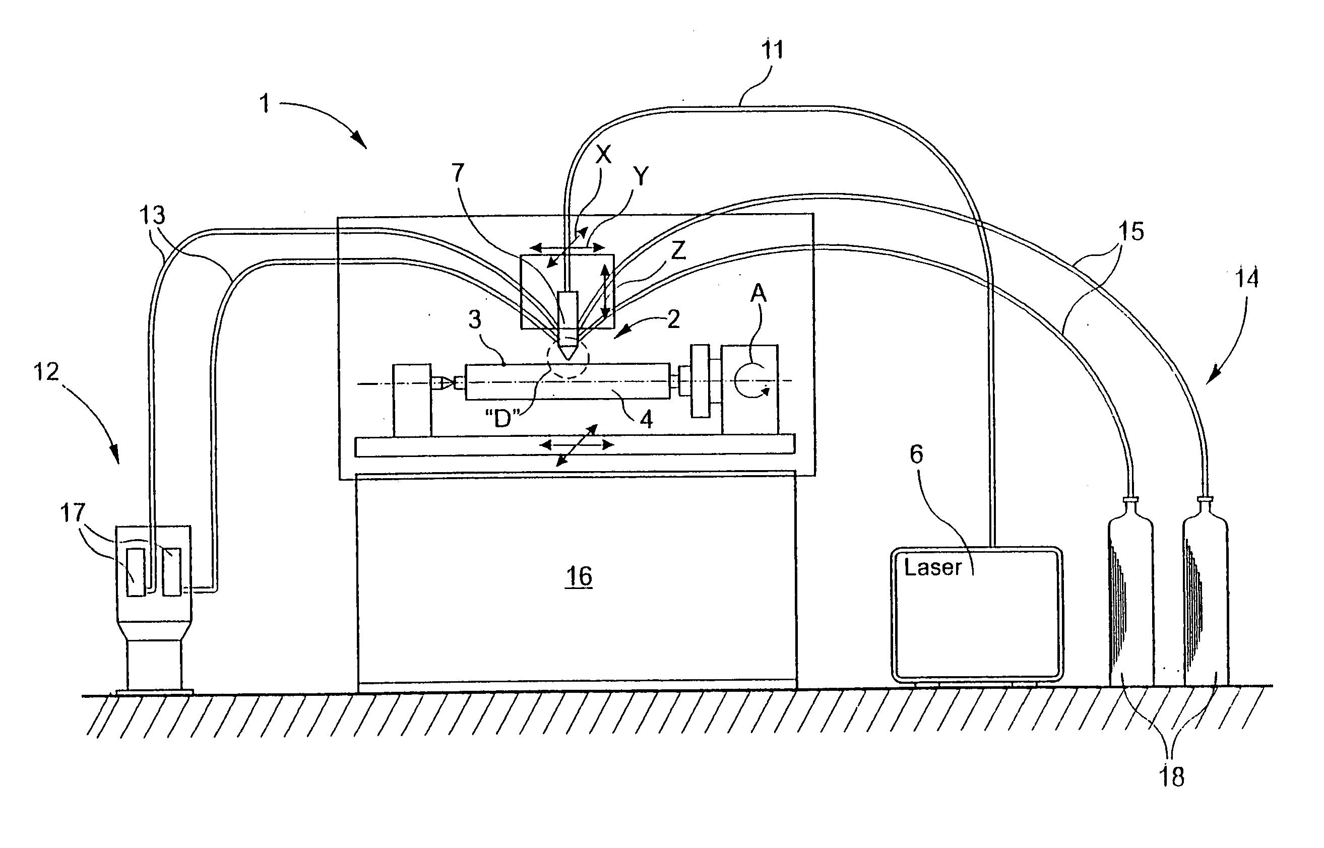
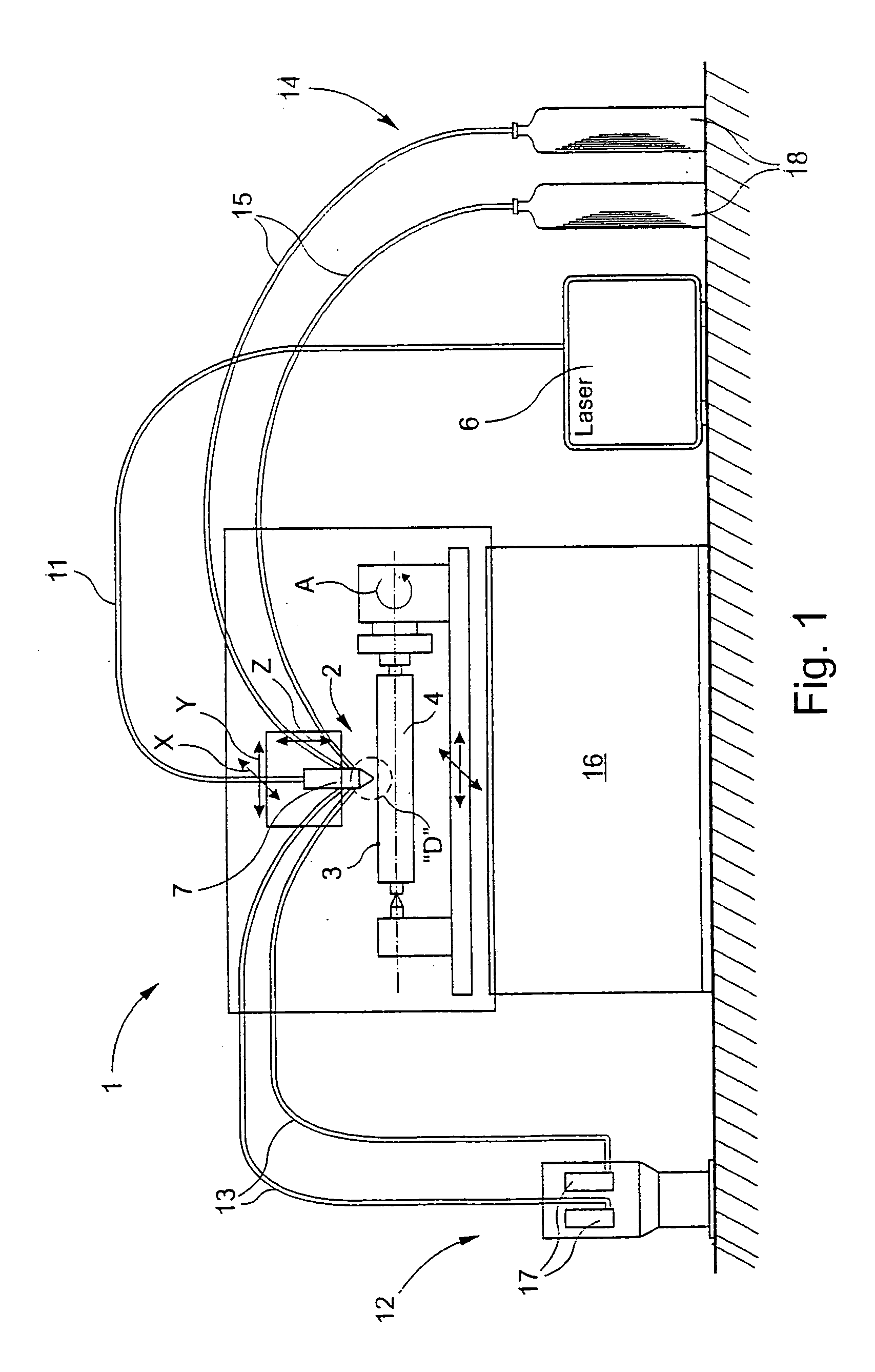
[0034] Turning now in detail to the drawings, FIG. 1 shows a device 1 for producing a cutting roller 2 having a cutting knife 5 that projects out of the surface 3 of a base body 4 of the roller. The cutting knife 5, which is also referred to as a knife blade, can be seen in FIG. 3. Cutting roller 2 is particularly used in envelope and label production machines.

[0035] Device 1 has a working head 7 that is mounted in a machine tool 16, preferably one that is computerized numerically-controlled (CNC controlled), and can be moved relative to the cylindrical base body 4 of the roller, which can be clamped in place so as to rotate about an axis of rotation A, in three spatial directions X, Y, and Z that stand perpendicular to one another, and are characterized with corresponding arrows in FIG. 1. Alternatively, working head 7 may be fixed in place, and base body 4 of the roller moved in the three spatial directions X, Y, and Z, relative to the fixed working head 7, and rotated about axis...


PUM

PropertyMeasurementUnit
Wavelengthaaaaaaaaaa

Abstract

A method for producing a cutting or embossing roller having a cutting knife or embossing projection that projects out of the surface of a base body of the roller ensures the greatest possible optimal homogeneity of the cutting knife or the embossing projection, while minimizing production duration and costs. Single-layer or multi-layer application of the cutting knife or the embossing projection onto the roller base body occurs by laser resurfacing welding. Each layer is produced using an additional powdered material, which is melted in a melt bath at the weld point. The heat and / or light radiation emitted by the melt bath is detected, at least during application of each layer. Laser power is controlled or regulated as a function of the heat and / or light radiation emitted by the melt bath, so that melt bath temperature remains essentially constant during application of each layer.

Description

CROSS REFERENCE TO RELATED APPLICATIONS [0001] Applicant claims priority under 35 U.S.C. §119 of German Application No. 10 2004 042 492.6 filed Aug. 31, 2004. BACKGROUND OF THE INVENTION [0002] 1. Field of the Invention [0003] The present invention relates to a method and a device for producing a cutting or embossing roller by means of laser resurfacing welding, particularly for use in an envelope or label production machine, for cutting or embossing moving material webs or moving individual cutouts. The invention furthermore relates to a cutting or embossing roller produced using this method. The invention also relates to the use of a powder composition for producing a cutting or embossing roller of this type, by means of laser resurfacing welding. [0004] 2. The Prior Art [0005] In envelope or label production machines, cutting or embossing rollers rotate at a relatively high speed of rotation, in order to perform cuts or embossed regions on moving webs of paper or moving individua...

Claims


Application Information

Patent Timeline
IPC IPC(8): B26D1/00B23D25/12B26D1/12
CPCB22F3/1055Y10T29/49561B23K26/03B23K26/032B23K26/034B23K26/123B23P15/406B26D1/0006B26D1/405B26D2001/002B26F1/384B26F1/44B26F2001/4436C22C1/0433C22C33/02B22F2998/00Y10T29/4956B22F2003/1056B23K26/3206B23K26/3273B23K26/345B23K35/30B23K35/3033B23K35/3046B23K35/3053B23K35/327B23K35/383B23K35/0244Y10T29/49544B22F3/003B23K26/32B23K26/342B23K2103/50B23K2103/52Y10T83/04Y10T83/9384Y10T83/9387Y10T83/9382Y10T83/4838Y02P10/25B22F12/41B22F12/222B22F12/226B22F12/53B22F12/224B22F12/90B22F10/25B22F10/368B22F12/44
Inventor CLOSMANN, MICHAEL
Owner WINKLER DUNNEBIER GMBH
Learn More