

Image display apparatus
a technology of image display and display screen, which is applied in the direction of discharge tube luminescnet screen, vacuum obtaining/maintenance, tubes with screens, etc., can solve the problems of reducing the electron emission amount, hindering the display of bright images, and adversely affecting electron sources, etc., to achieve high reliability, low leakage, and high display grade
- Summary
- Abstract
- Description
- Claims
- Application Information
AI Technical Summary
Benefits of technology
Problems solved by technology
Method used
Image

Examples
example 1
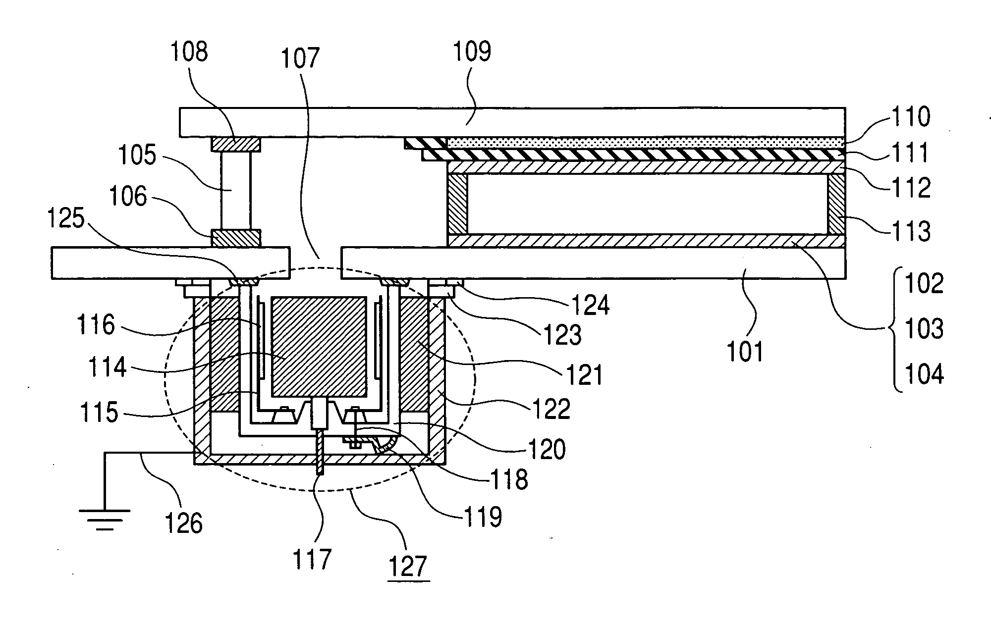
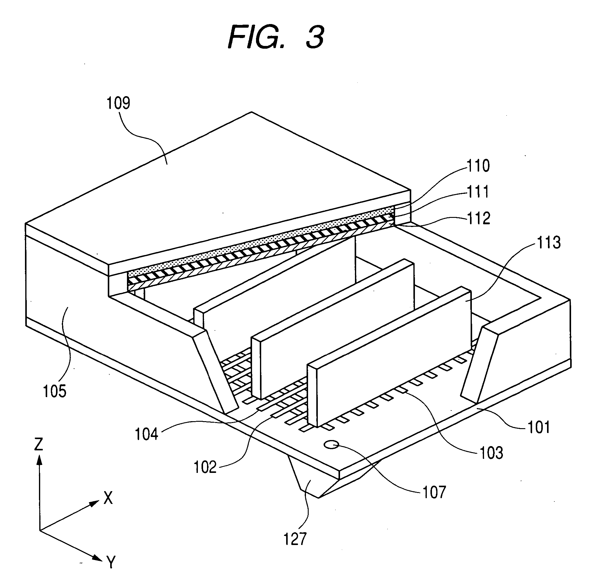
[0111] An image display apparatus having an ion pump will be explained referring to FIG. 1, and the configuration and the production method of a vacuum chamber as the image display apparatus referring to FIGS. 3 to 7.
[0112] First of all, a method for producing an image display apparatus of a sealed vessel will be described. Soda glass (SL: product made by Nippon Sheet Glass Co., Ltd.) with a thickness of 2.8 mm and a size of 190×270 mm was used as a face plate 201, and the same soda glass with a thickness of 2.8 mm and a size of 240×320 mm was used as a rear plate 101. In the practically used rear plate 101, an outlet 107 with a diameter of 8 mm was opened at a position outside an image region and on the inside of a glass frame 105.
[0113] The film of element electrodes 402 and 403 in a surface conduction type electron-emitting device 104 which is an electron source was formed by forming a film of platinum on a rear plate 101 with a vapor deposition method, and processing the film ...
example 2
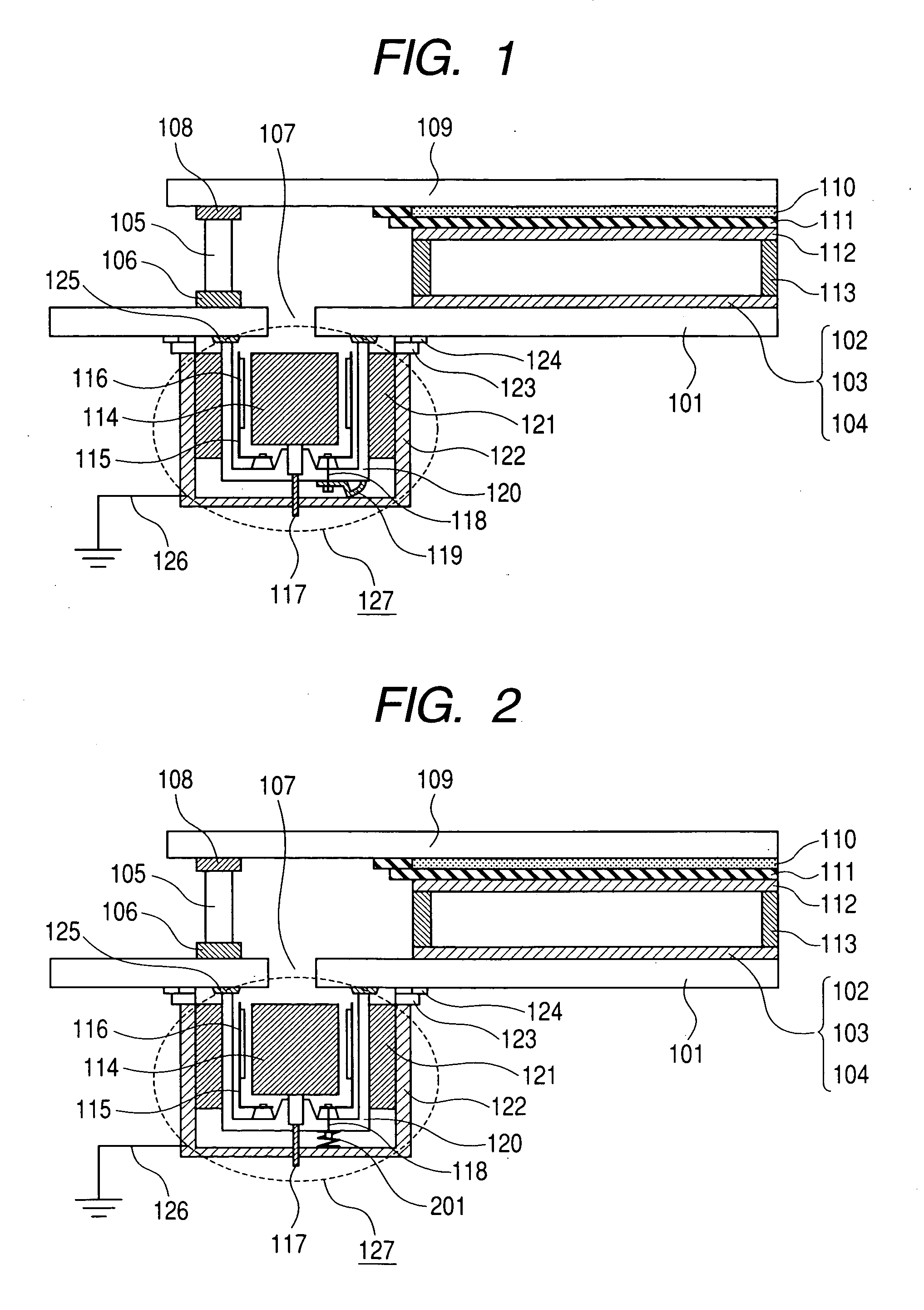
[0141] In Example 2, an image display apparatus having an ion pump 127 was prepared similarly to Example 1 except that a coiled spring 201 was used as a spring for connecting a cathode connecting terminal 118 to an ion pump chamber 120.
[0142] Subsequently, an image display apparatus was assembled by the steps of: connecting a sealed vessel to a voltage-applying device and a high-voltage-applying device with a cable so that the sealed vessel can display images; and further connecting a cathode connecting terminal 118 and an anode connecting terminal 117 of an ion pump 127 to an ion pump power source with wires.
[0143] Then, the voltage of 5 KV was applied to an ion pump power source, and an ion pump 127 was driven with a magnetic field of 1,400 G or more in a center of the ion pump. In addition, picture signals having the conditions of 16.7 μsec, 60 Hz and 15 V were supplied to an electron-emitting device from a voltage-applying device connected to an image display apparatus, at the...
example 3
[0148] In an Example 3, an image display apparatus using a field emission type electron-emitting device as an electron source will be described. FIG. 8 shows a structure of the field emission type electron-emitting device 80 used in the present example. In the figure, reference numeral 802 denotes a negative electrode, reference numeral 803 a positive electrode, reference numeral 805 an electron-emitting portion for emitting electrons, of which the tip is formed into an acute angle, and reference numeral 804 an insulating layer. In such a configuration, when voltage is applied to the positive electrode 803 and the negative electrode 802 so that the positive electrode 803 can have a high potential, an electric field is concentrated in the electron-emitting portion 805 and the electrons are emitted from the electron-emitting portion 805 by a tunnel effect.
[0149] A method for producing an image display apparatus in the present example will be described below. At first, a field emissio...
PUM
 Abstract
Description
Claims
Application Information