[0009] Accordingly, the present invention provides a hydraulic regenerative braking system that can conserve space by using fixed displacement, or limited
variable displacement, pump-motors.
[0011] The invention further provides a hydraulic pump-motor that includes a
cam for actuating the pistons, where the
cam is disposed inboard of the pistons, thereby conserving space by providing a smaller pump-motor.
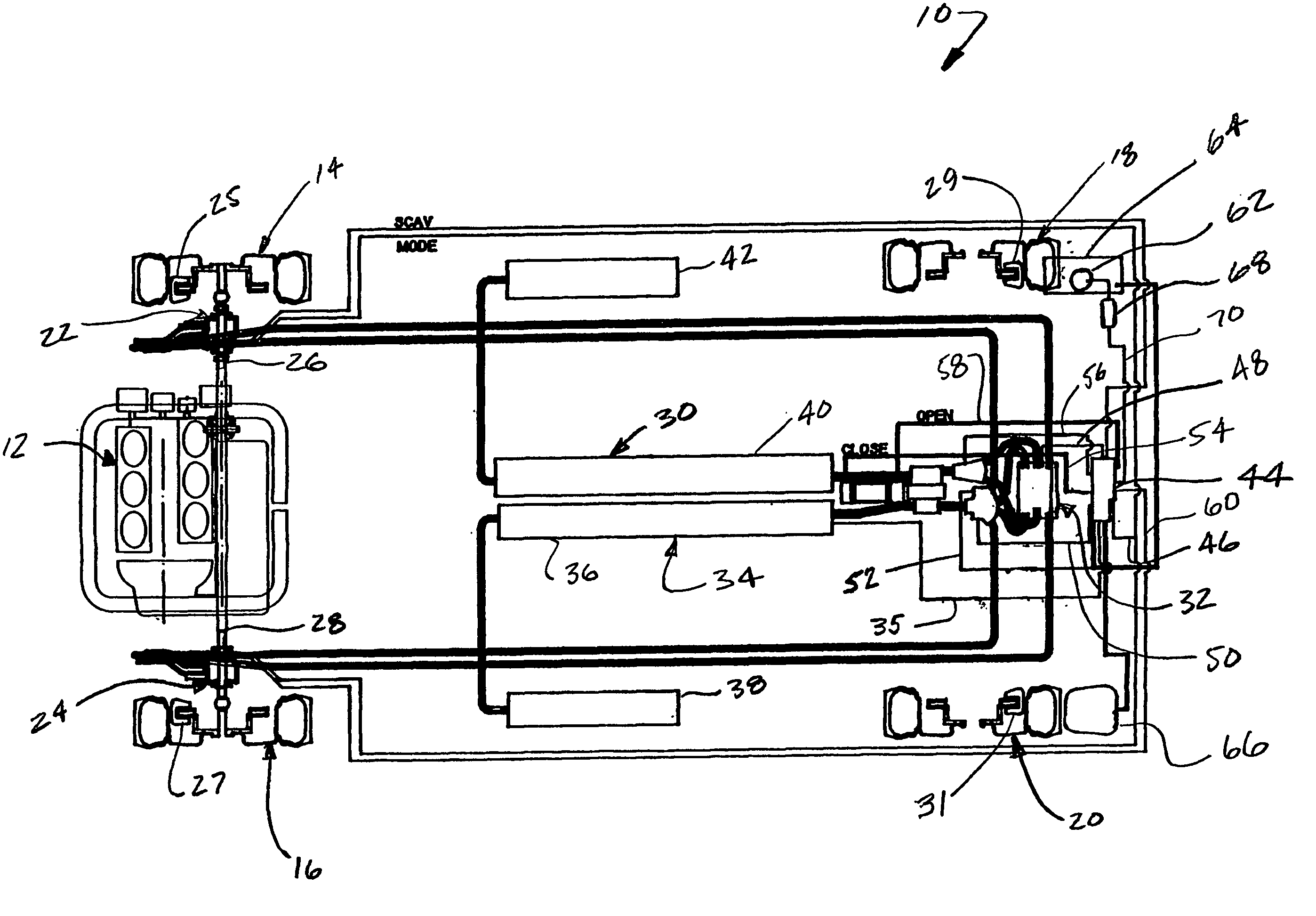
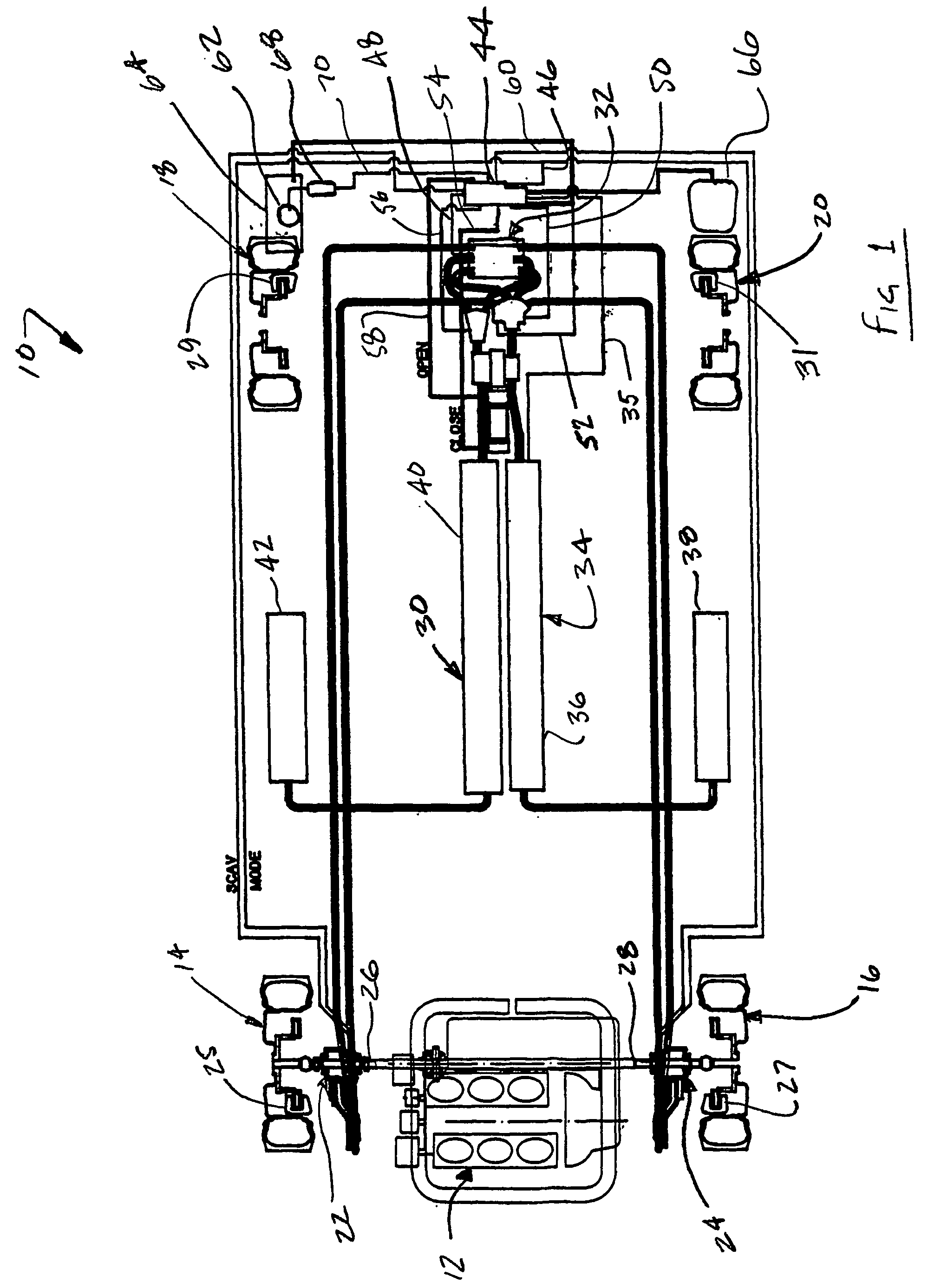
[0012] The invention also provides a hydraulic regenerative braking system for a vehicle. The system includes at least one hydraulic
machine operable as a pump configured to be driven by energy received from at least one vehicle wheel when the vehicle is braking, thereby facilitating storage of
vehicle braking energy. The at least one hydraulic
machine is further operable as a motor configured to be driven by stored braking energy, thereby providing torque to at least one vehicle wheel. A first accumulator is configured to receive fluid from the at least one hydraulic
machine, and to store the fluid under pressure. The first accumulator is further configured to provide pressurized fluid to the at least one hydraulic machine, thereby facilitating use of the hydraulic machine as a motor. A second accumulator is configured to store pressurized fluid and to provide a charge pressure to an inlet of the at least one hydraulic machine. A
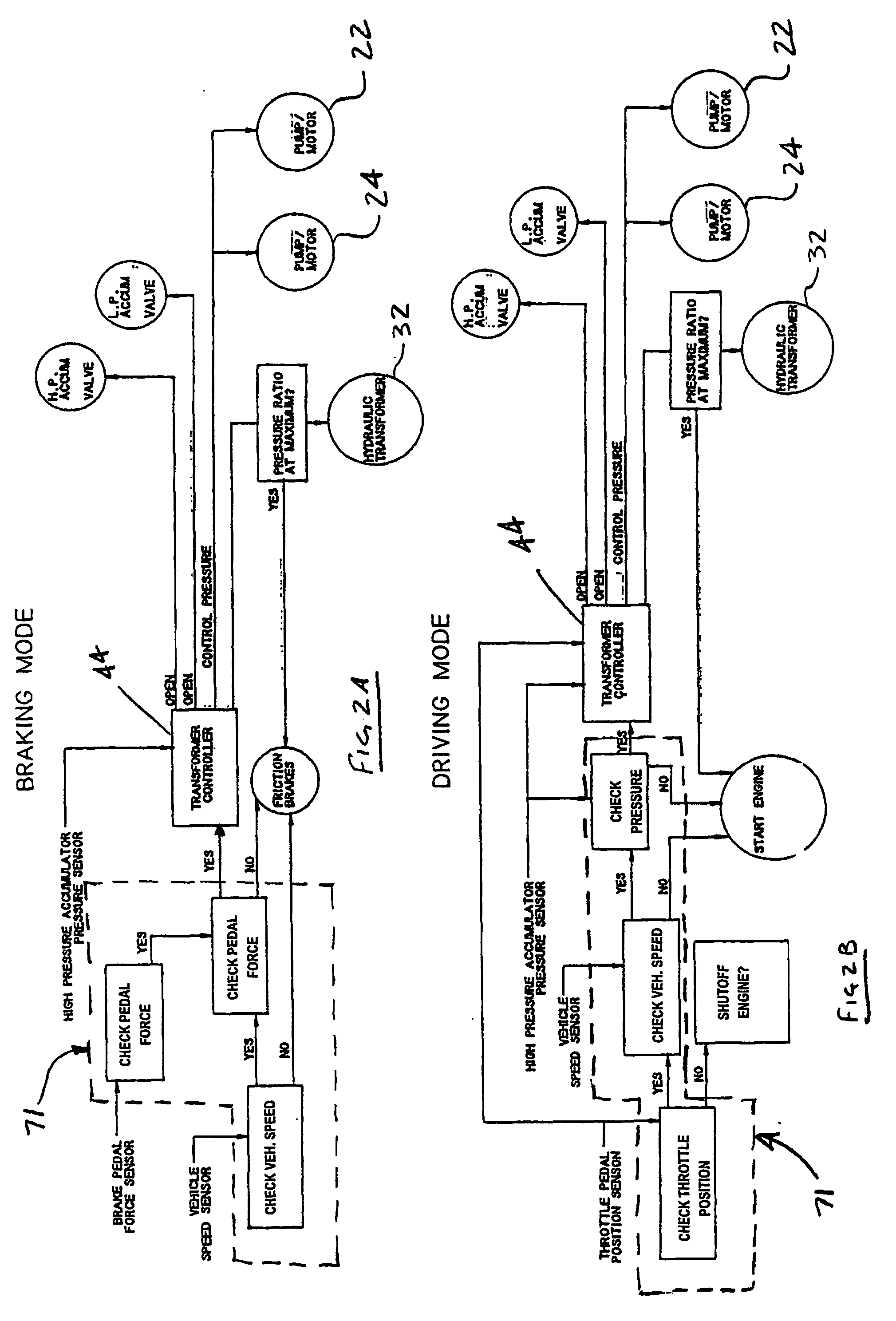
variable ratio transformer is in communication with the first and second accumulators and the at least one hydraulic machine. The transformer is operable to vary the pressure of the pressurized fluid provided to the at least one hydraulic machine, thereby facilitating variation in the torque provided to the at least one vehicle wheel. The transformer is further operable to vary the pressure of the fluid received by the first accumulator. A control module is configured to receive inputs related to operation of the vehicle, and to control operation of the transformer. The inputs include an acceleration request and a braking request.
[0013] The invention further provides a hydraulic machine operable as a pump configured to be driven by a rotating shaft, thereby increasing the pressure of fluid flowing through the pump. The hydraulic machine is further operable as a motor configured to be driven by pressurized fluid, thereby providing torque to a shaft. The hydraulic machine includes a housing, including a
high pressure fluid port and a low pressure fluid port. The hydraulic machine also includes a plurality of radial pistons. Each of the pistons is configured to reciprocate within a corresponding cylinder in the housing, thereby pumping fluid when the hydraulic machine is operating as a pump, and providing torque when the hydraulic machine is operating as a motor. Each of the pistons includes a corresponding
cam follower. A cam is disposed within the housing, and has a plurality of external lobes configured to cooperate with the cam followers to translate rotational motion of the cam into
linear motion of the pistons when the hydraulic machine is operating as a pump, and to translate
linear motion of the pistons into rotational motion of the cam when the hydraulic machine is operating as a motor. The cam includes an aperture therethrough for receiving a rotatable shaft. A rotatable valve plate has a plurality of apertures therethrough; at least some of the apertures communicate with the
high pressure fluid port and at least some of the apertures communicate with the low pressure fluid port. The valve plate is configured to provide a fluid path between the cylinders and the
high pressure fluid port when corresponding pistons are in a
power stroke and between the cylinders and the low pressure fluid port when corresponding pistons are in an exhaust
stroke, thereby facilitating operation of the hydraulic machine as a motor. The valve plate is further configured to provide a fluid path between the cylinders and the high pressure fluid port when corresponding pistons are in an exhaust
stroke and between the cylinders and the low pressure fluid port when corresponding pistons are in a
power stroke, thereby facilitating operation of the hydraulic machine as a pump.
[0015] The invention further provides a compact hydraulic machine operable as a pump and a motor, and configured to be disposed on a
vehicle driving shaft
proximate a vehicle wheel. The hydraulic machine includes a housing which has a first housing portion, a second housing portion, and an outer ring. The first housing portion includes a high pressure fluid port and a low pressure fluid port. The second housing portion includes a plurality of radially oriented cylinders disposed therein, and the outer ring includes a tapered bore to facilitate sealing of each of the cylinders. The hydraulic machine also includes a plurality of pistons, each of which includes a
cam follower, and each of which is configured to reciprocate within a corresponding cylinder. A cam is disposed within the housing, and has a plurality of external lobes configured to cooperate with the cam followers to translate rotational motion of the cam into
linear motion of the pistons when the hydraulic machine is operating as a pump, and to translate linear motion of the pistons into rotational motion of the cam when the hydraulic machine is operating as a motor. The cam includes an aperture therethrough for receiving a rotatable shaft. A rotatable valve plate has a plurality of apertures therethrough, and is configured to selectively connect the cylinders with the low and high pressure fluid ports, thereby alternately facilitating operation of the hydraulic machine as a pump and a motor.

