

Adaptive pre-equalization method and apparatus
- Summary
- Abstract
- Description
- Claims
- Application Information
AI Technical Summary
Benefits of technology
Problems solved by technology
Method used
Image

Examples
Embodiment Construction
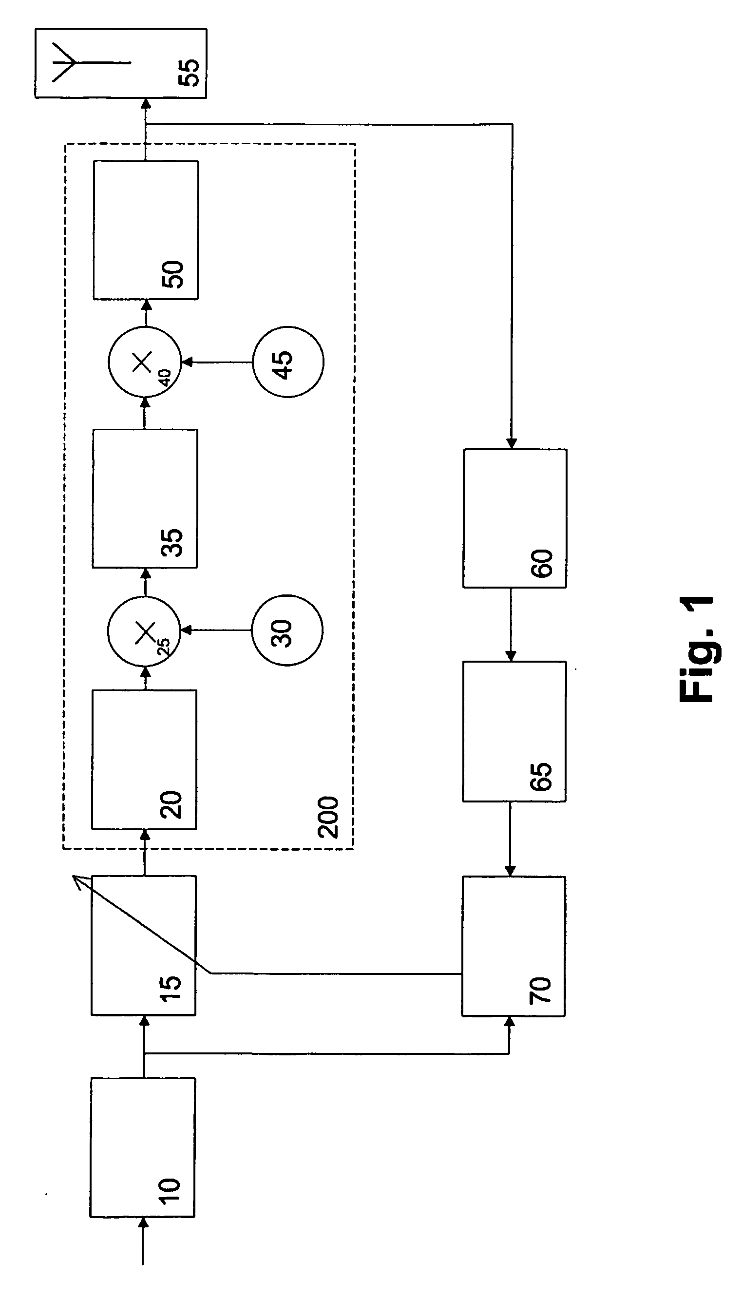
[0029] The preferred embodiment of the present invention will now be described on the basis of a heterodyne OFDM transmitter architecture for an IEEE 802.11a wireless LAN transmitter architecture as shown in FIG. 1.
[0030] According to FIG. 1, an input signal which may be based on a binary phase shift keying (BPSK), a quadrature phase shift keying (QPSK) or a quadrature amplitude modulation (QAM) is up-converted and low-pass filtered before being supplied in the digital domain to a digital intermediate frequency (IF) circuit 10 at an intermediate frequency of e.g. 20 MHz. The generated IF signal is supplied to an adaptive pre-equalizer 15 arranged to pre-equalize the signal stream such that the distortions generated by non-ideal analog filter circuits of the following stages results again in an accurate signal stream. The pre-equalized signal is supplied to a transmitter circuitry 200, in which the signal is processed for transmission via a transmission antenna 55.
[0031] The transm...
PUM
 Abstract
Description
Claims
Application Information