Method and apparatus for improving both lateral and axial resolution in ophthalmoscopy

a technology of ophthalmoscopy and lateral resolution, applied in the field of optical imaging methods and equipment, can solve the problems of untapped potential benefits of observing retinal cells, difficult retinal microscopy, and less than 0.2% of human retinal cells being visualized

Active Publication Date: 2006-03-16
UNIVERSITY OF ROCHESTER
View PDF11 Cites 119 Cited by
  • Summary
  • Abstract
  • Description
  • Claims
  • Application Information

AI Technical Summary

Benefits of technology

[0008] The invention provides a method and apparatus for optical imaging of tissue by combining the techniques of optical coherence tomography (OCT) and adaptive optics (AO). In one aspect, the invention is directed to a method of optical imaging comprising providing a sample to be imaged, measuring and correcting aberrations associated with the sample using AO, and imaging the sample by OCT. In another aspect, the invention is further directed to an optical imaging system comprising an OCT system that is modified with a wavefront corrector and wavefront sensor for pe

Problems solved by technology

Yet despite major advances in retinal cameras, less than 0.2% of human retinal cells have been visualized in vivo and the potential benefit of observing these cells has remained untapped.
Retinal microscopy is extremely challenging because (1) optical aberrations primarily in the cornea and crystalline lens substantially blur the retinal image and (2) reflections from cells at many different depths in the thick retina are weak and create a host of superimposed images at the detector.
The AO camera,

Method used


Image

  • Method and apparatus for improving both lateral and axial resolution in ophthalmoscopy
  • Method and apparatus for improving both lateral and axial resolution in ophthalmoscopy
  • Method and apparatus for improving both lateral and axial resolution in ophthalmoscopy

Examples


example 1

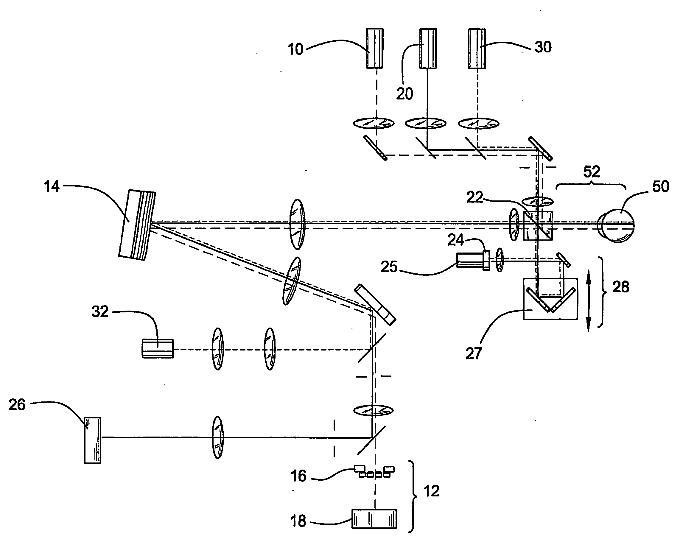
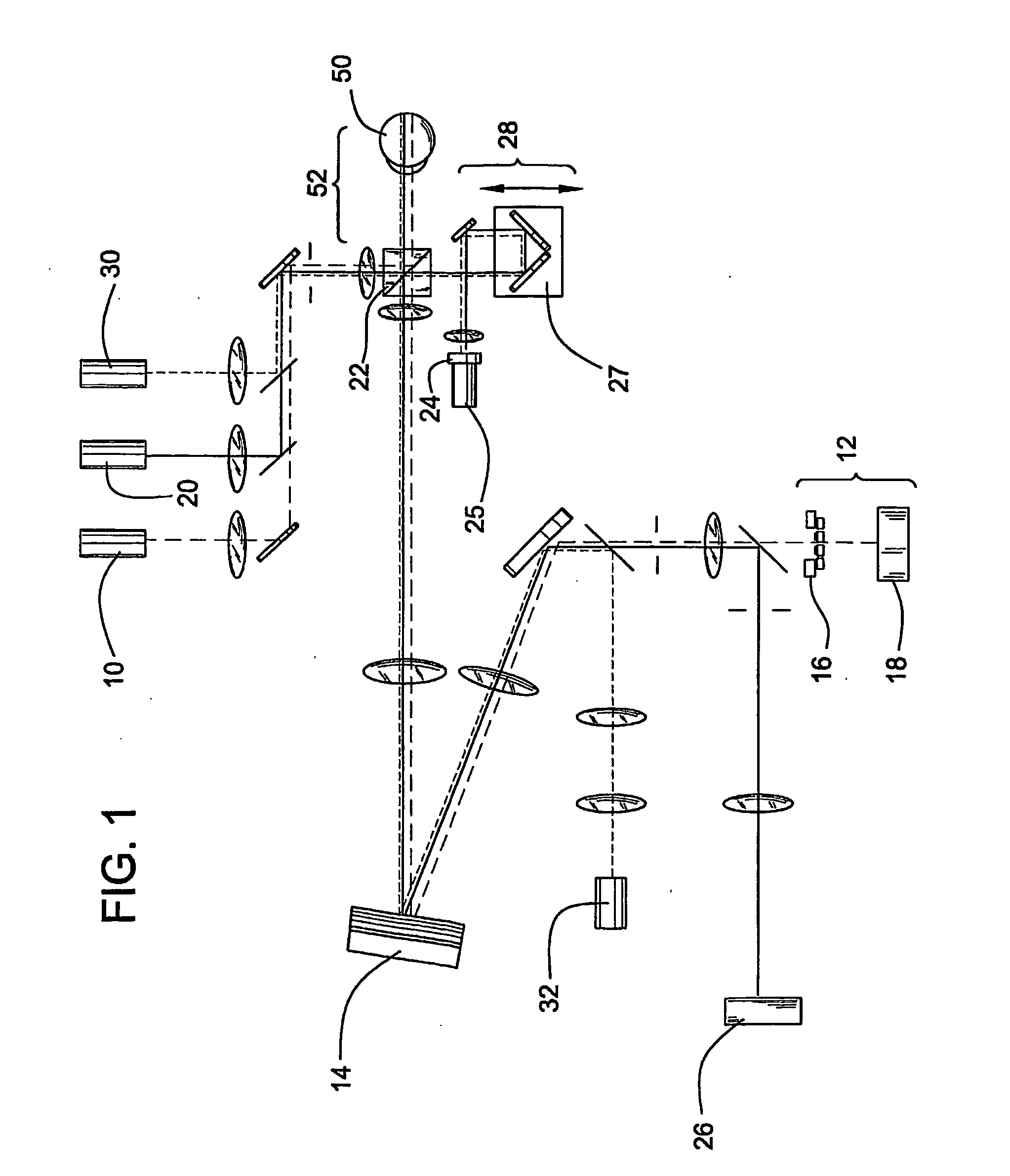
[0057] This example demonstrates a method of optical imaging that combines optical coherence tomography and adaptive optics.

[0058] A parallel OCT system based on a free-space Michelson interferometer design was constructed. The OCT system comprised a superluminescent diode having a wavelength (λ) of 679 nm, a voice coil and piezo-electric translators (Polytec PI, Auburn, Mass.) for adjusting the OPL of the reference channel, and a scientific grade 12-bit CCD array camera for detecting and recording the 2D interferograms. En-face image slices of an in vitro bovine retina were obtained using a four-step phase shift reconstruction method. The system collected four images over a 7 msec time period. Each image required a 1 msec duration followed by a 1 msec delay to allow λ / 8 movement of the piezo-electric reference mirror, corresponding to a λ / 4 phase delay. The dynamic range of the OCT system was measured by positioning a planar mirror in the sample channel and sweeping the reference ...

example 2

[0061] This example illustrates the optical imaging method of the invention comprising the use of an AO-OCT retina camera

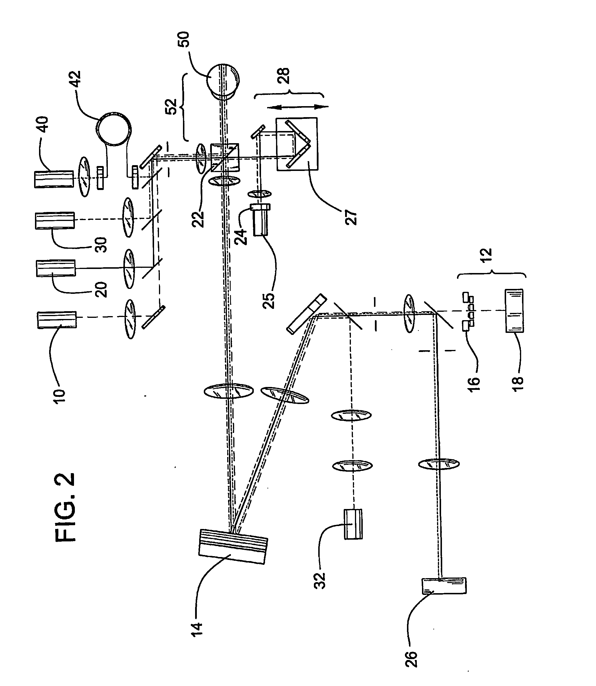
[0062] AO-OCT Camera Description: An AO-OCT retina camera was developed based on a free-space Michelson interferometer design. A flood-illuminated en face OCT scheme was chosen that acquired aerial images of the retina with a scientific-grade CCD camera. A major strength of this parallel approach was its insensitivity to retinal motion blur as thousands of points could be collected simultaneously. An additional advantage was its compatibility with adaptive optics. The camera consisted of four independent yet highly synchronized subsystems to perform AO, 2D low coherent flood illumination imaging, 2D en face OCT imaging, and 1D-OCT axial scanning. Each subsystem is described below.

[0063] AO Subsystem: The AO subsystem consisted of a 37 actuator Xinetics mirror and a Shack-Hartmann wavefront sensor employing a 17×17 lenslet array. Light from a 788 nm SLD enters th...


PUM


Abstract

The invention provides a method of optical imaging comprising providing a sample to be imaged, measuring and correcting aberrations associated with the sample using adaptive optics, and imaging the sample by optical coherence tomography. The method can be used to image the fundus of a human eye to provide diagnostic information about retinal pathologies such as macular degeneration, retinitis pigmentosa, glaucoma, or diabetic retinopathy. The invention further provides an apparatus comprising an adaptive optics subsystem and a two-dimensional optical coherence tomography subsystem.

Description

CROSS-REFERENCE TO RELATED PATENT APPLICATIONS [0001] This patent application claims the benefit of U.S. Provisional Patent Application No. 60 / 388,036, filed Jun. 12, 2002, which is incorporated herein by reference.STATEMENT REGARDING FEDERALLY SPONSORED RESEARCH AND DEVELOPMENT [0002] This invention was made in part with Government support under Grant Number AST-9876783 awarded by the National Science Foundation. The Government may have certain rights in this invention.FIELD OF THE INVENTION [0003] This invention pertains to an optical imaging method and apparatus. More particularly, the invention relates to the imaging of biological tissue, such as retinal and ocular tissue, preferably at the cellular level, with high quality lateral and axial resolution. BACKGROUND OF THE INVENTION [0004] The human retina is exceedingly thin, yet its 1 / 100th of an inch thickness supports a vast microcosm of diverse cells organized in discrete layers, each playing a critical role in the visual pro...

Claims


Application Information

Patent Timeline
IPC IPC(8): A61B6/00A61B3/113A61B3/12G01B9/02
CPCA61B3/102G01B9/02007G01B9/02003G01B2290/45G01B9/02068G01B9/02038G01B9/02091
Inventor MILLER, DONALD T.JONNAL, RAVISQU, JUNLETHORN, KARENE
Owner UNIVERSITY OF ROCHESTER
Why Eureka
Try Eureka