Phosphor and an incandescent lamp color light emitting diode lamp using the same

a technology of incandescent lamps and diodes, which is applied in the direction of discharge tubes/lamp details, discharge tubes luminescent compositions, discharge tubes/lamp details, etc., can solve the problems of increasing the demand for illumination apparatuses that emit low color temperature light, waste disposal of conventional general illumination apparatuses of various types, and inability to emit, etc., to achieve the effect of reducing the number of lamps

Active Publication Date: 2006-03-23
THE FUJIKURA CABLE WORKS LTD +1
View PDF13 Cites 25 Cited by
  • Summary
  • Abstract
  • Description
  • Claims
  • Application Information

AI Technical Summary

Benefits of technology

[0053] According to the present invention, there is provided an incandescent lamp color light emitting diode lamp that has a high emission efficiency and an appropriate chromaticity. In addition, there is provided a phosphor that enables

Problems solved by technology

However, conventional general illumination apparatuses of various types have a problem of waste disposal since they contain substances that impose a heavy burden on the environment such as mercury or the like and require an improved power efficiency.
While a semiconductor illumination apparatus, specifically, a white light emitting diode lamp is expected to solve such problems, the white light emitting diode lamp in a mainstream that is composed of a blue light emitting diode and a Ce-activated YAG phosphor cannot emit a low color temperature light such as incandescent lamp color due to a deficiency of red component of the spectrum.
Thus, an increasing demand for

Method used


Image

  • Phosphor and an incandescent lamp color light emitting diode lamp using the same
  • Phosphor and an incandescent lamp color light emitting diode lamp using the same
  • Phosphor and an incandescent lamp color light emitting diode lamp using the same

Examples


first embodiment

A First Embodiment

[0222]FIG. 21 is a cross-sectional view of an artillery shell type light emitting diode lamp 1a according to a first embodiment (Embodiment 1). FIG. 22 is a perspective view of the artillery shell type light emitting diode lamp 1a.

[0223] First, a phosphor 11 in those figures will be described.

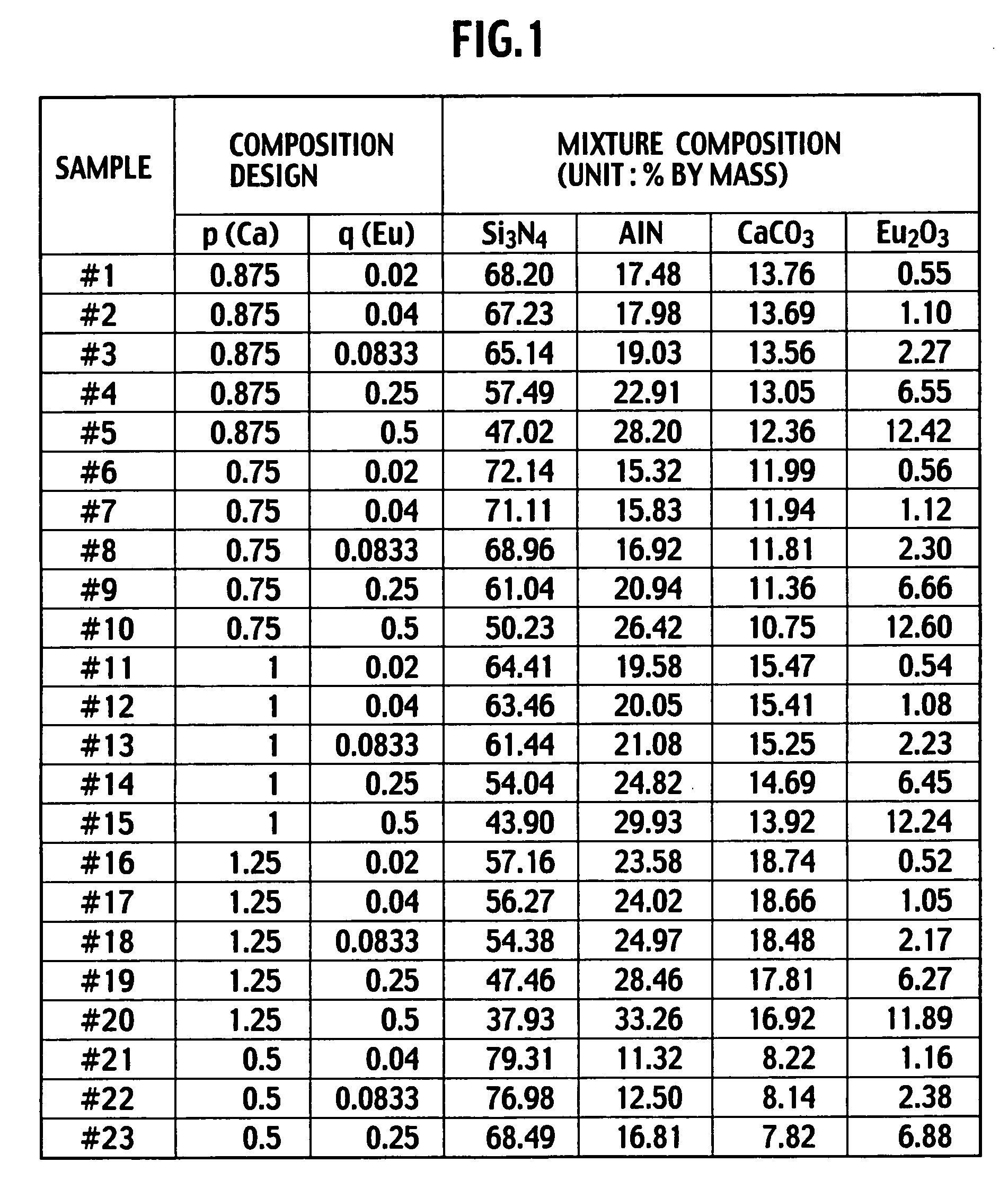
[0224] A composition of the phosphor 11 is designed as Ca0.875Si90.06Al2.940O0.98N15.02:Eu2+0.07, which is the same as the sample F.

[0225] As starting materials, 65.78 wt % of α-Si3N4, 18.71 wt % of AlN, 13.59 wt % of CaCO3, and 1.91 wt % of Eu2O3 were weighed and charged into a container made of Silicon Nitride along with n-hexane as solvent and balls made of Silicon Nitride. Next, the materials were wet-mixed by a planetary ball mill for 2 hours at 150 rotations per minute (rpm).

[0226] Then, the mixed materials were dried by a rotary evaporator and then the dried materials in powder form were pounded well in a mortar. Next, the pounded materials were granulated using a s...

second embodiment

A Second Embodiment

[0252] Next, a light emitting diode lamp according to a second embodiment (Embodiment 2) will be described. This light emitting diode lamp has the same structure as the artillery shell type light emitting diode lamp according to the first embodiment except for the following. Namely, the light emitting diode lamp according to the second embodiment uses a blue light emitting diode chip with higher emission efficiency than the blue light emitting diode chip used in the artillery shell type light emitting diode lamp according to the first embodiment and is fabricated by a slightly improved packaging process of the blue light emitting diode chip, thereby realizing an improvement in external emission efficiency. By the way, it is needless to say that the phosphor used is the sample Y6 in the artillery shell type light emitting diode lamp according to the first embodiment.

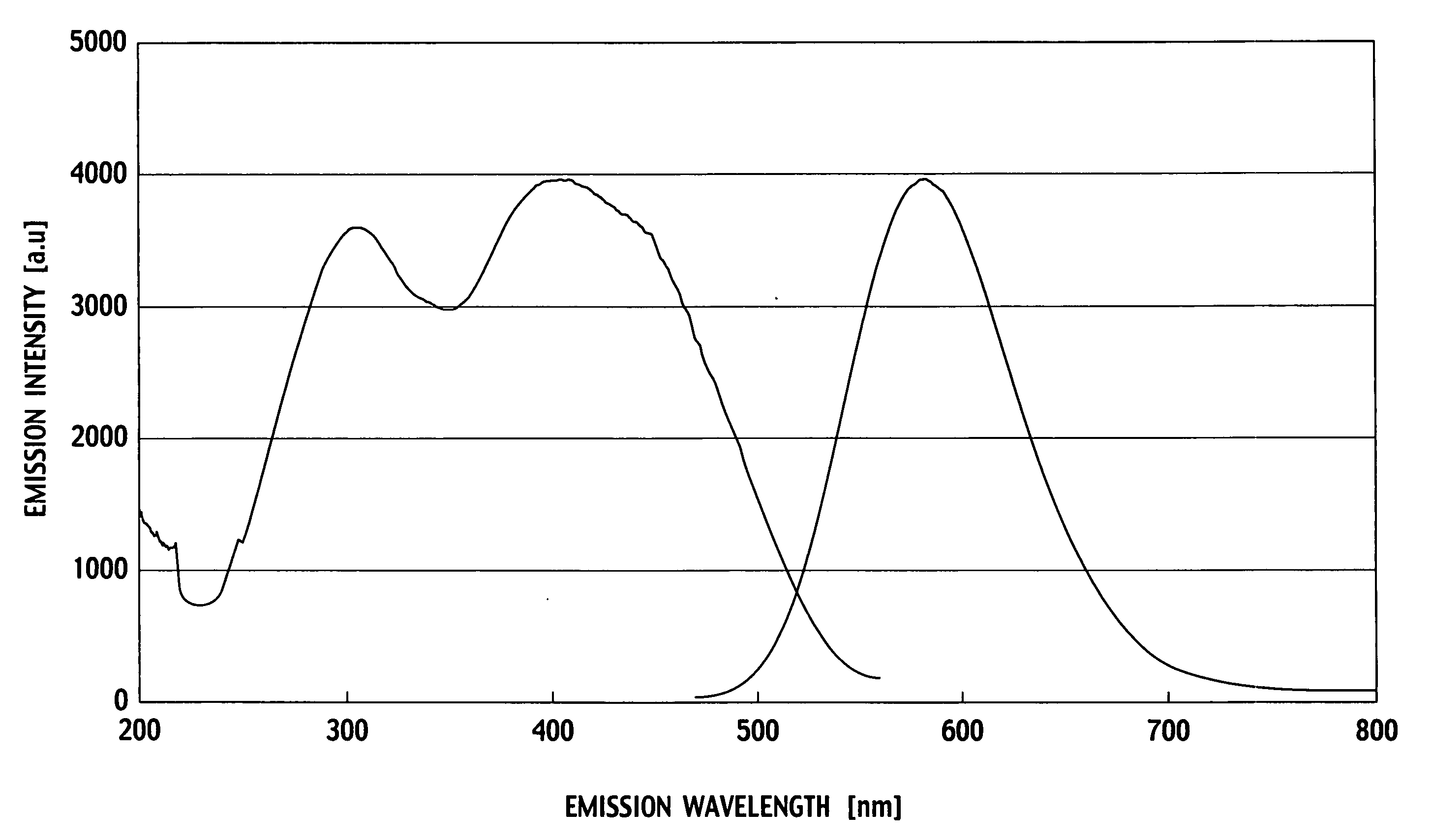
[0253]FIG. 27 illustrates an emission spectrum J of the light emitting diode lamp according to the ...

third embodiment

A Third Embodiment

[0255]FIG. 28 is a cross-sectional view of an artillery shell type light emitting diode lamp 1b according to a third embodiment (Embodiment 3) of the present invention. FIG. 29 is a perspective view of the artillery shell type light emitting diode lamp 1b.

[0256] In case of the artillery shell type light emitting diode lamp 1a illustrated in FIGS. 21 and 22, the phosphor 11 is dispersed in the vicinities of the blue light emitting diode chip 5, that is, in the resin 12. However, this does not limit the present invention. The artillery shell type light emitting diode lamp can be configured in such a way that the phosphor 11 is dispersed in resin 13, that is, entirely in the resin, as in this embodiment.

[0257] By the way, when fabricating the above artillery shell type light emitting diode lamp 1b, while the resin 12 is not cured, the phosphor 11 is dispersed in the resin 13 and then the resin 13 is cured.


PUM

PropertyMeasurementUnit
Temperatureaaaaaaaaaa
Fractionaaaaaaaaaa

Abstract

An incandescent lamp color light emitting diode lamp comprises a semiconductor blue light emitting diode chip having a center emission wavelength in a range of from 400 nm to 480 nm and a phosphor that absorbs light emitted from the diode chip to emit light having a different wavelength than the light emitted from the diode chip. The phosphor is represented by a general formula of Mp(Si, Al)12(O, N)16:Eu2+q. The main phase is an α-SiAlON phosphor having an α SiAlON structure, wherein M is at least one element of Ca, Y, Mg, Li, Sc, Pr, Nd, Pm, Sm, Gd, Tb, Dy, Ho, Er, Tm, Yb, Lu, and Sr and p is from 0.75 to 1.0; and q is between 0.02 and 0.09. The diode lamp emits light having an emission color produced by a mixture of the light emitted from the semiconductor blue light emitting and the light emitted from the α-SiAlON. The chromaticity range thereof falls within the range defined by chromaticity coordinates (x, y) of (0.4775, 0.4283), (0.4594, 0.3971), (0.4348, 0.4185), and (0.4214, 0.3887) on the XYZ chromaticity diagram.

Description

CROSS REFERENCE TO RELATED APPLICATION [0001] This application claims the benefit of priority under 35 U.S.C. § 119 to Japanese Patent Applications No. 2004-206509, filed on Jul. 13, 2004, and Japanese Patent Applications No. 2004-235945, filed on Aug. 13, 2004, the entire content of which is incorporated by reference herein. BACKGROUND OF THE INVENTION [0002] 1. Field of the Invention [0003] The present invention relates to a phosphor and an incandescent lamp color light emitting diode lamp using the same. [0004] 2. Description of the Related Art [0005] In a technological field of illumination, a solid-state illumination, specifically, a white light illumination using a semiconductor light emitting diode has attracted a lot of attention and thus researches and developments have been widely and vigorously performed on the lighting apparatus. [0006] A white light emitting diode lamp has attracted a lot of attention as a next generation illumination apparatus that replaces conventiona...

Claims


Application Information

Patent Timeline
IPC IPC(8): H01J1/62H01L33/32H01L33/50H01L33/56H01L33/62
CPCC04B35/597C04B35/6261H01L2224/45144H01L2224/8592H01L2224/73265H01L2224/48247H01L2224/48091H01L2224/32245H01L2224/32257C04B35/6262C04B35/62695C04B35/645C04B2235/3208C04B2235/3224C04B2235/3865C04B2235/3878C04B2235/442C04B2235/5427C09K11/0883C09K11/7734H01L33/502H05B33/14H01L2924/00014H01L2924/00H01L2924/181C09K11/77348H01L2924/00012C09K11/64C09K11/77
Inventor SAKUMA, KENOMICHI, KOJIKIMURA, NAOKIOHASHI, MASAKAZUTANAKA, DAIICHIROHIROSAKI, NAOTO
Owner THE FUJIKURA CABLE WORKS LTD
Why Eureka
Try Eureka