Flame spraying process and apparatus

a technology of spraying process and apparatus, applied in the direction of coating, sustainable transportation, plasma technique, etc., can solve the problems of high spray rate, low deposition rate of thermal spraying process, and difficulty in controlling the chemical environment and preventing

Inactive Publication Date: 2006-03-23
GJL PATENTS
View PDF62 Cites 19 Cited by
  • Summary
  • Abstract
  • Description
  • Claims
  • Application Information

AI Technical Summary

Benefits of technology

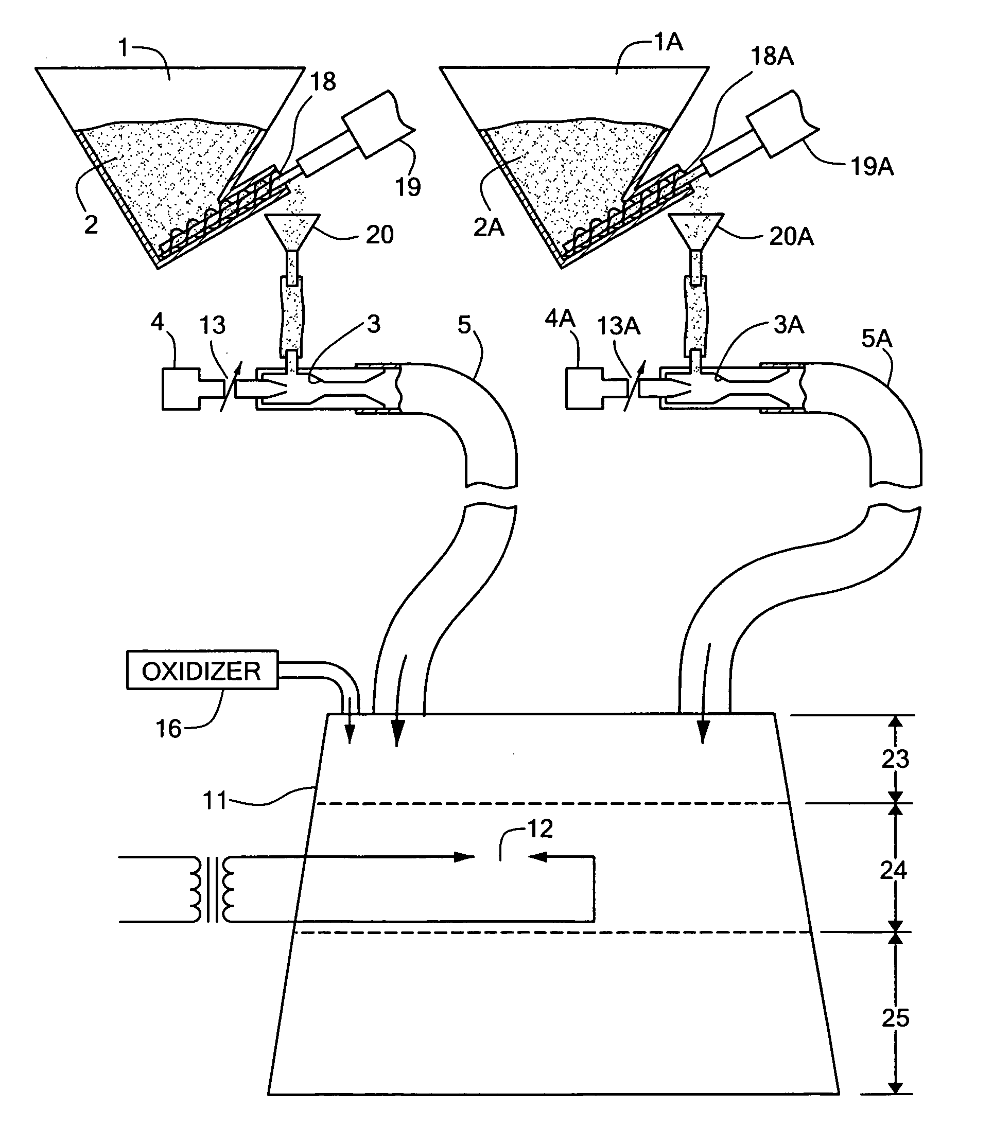
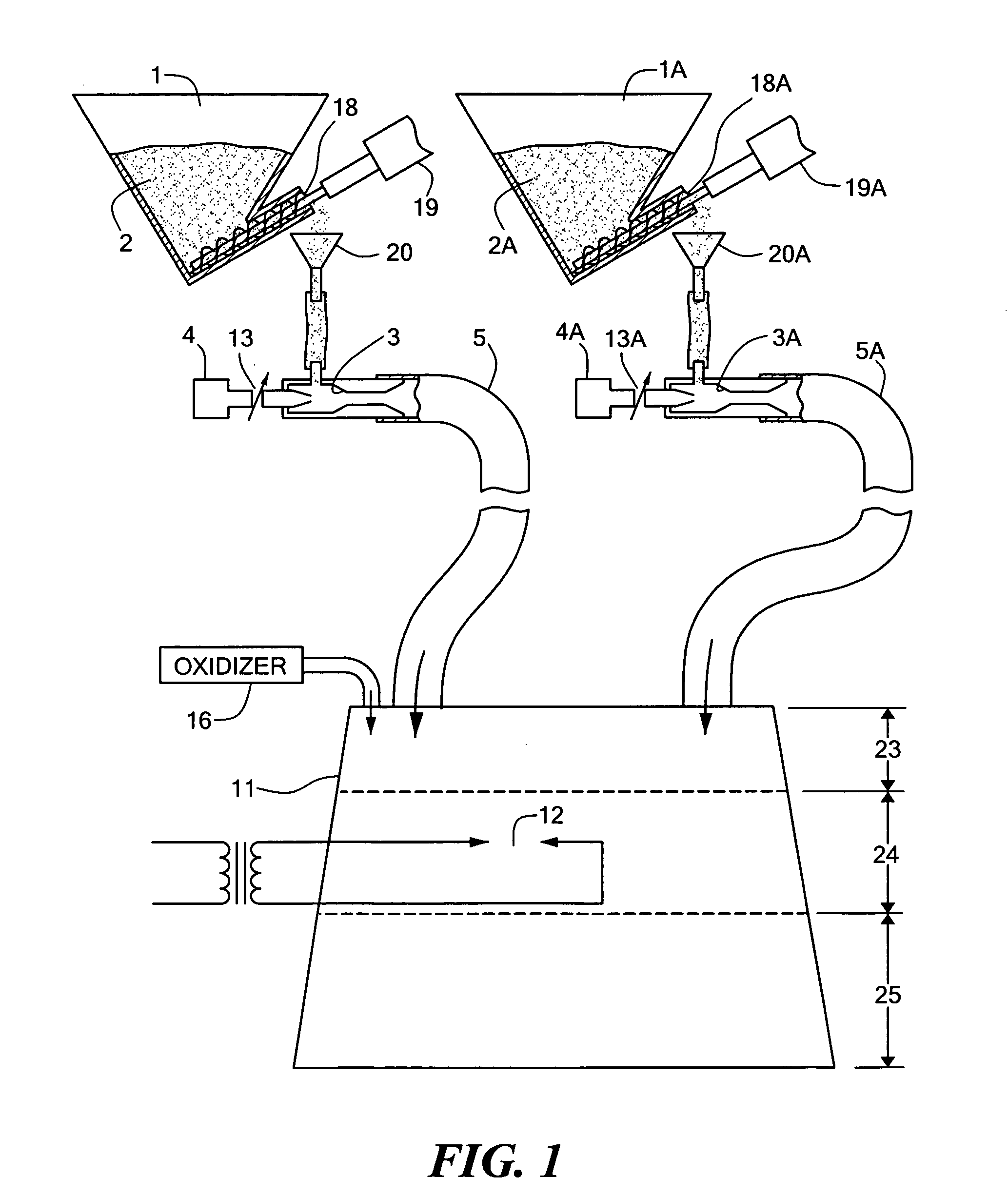
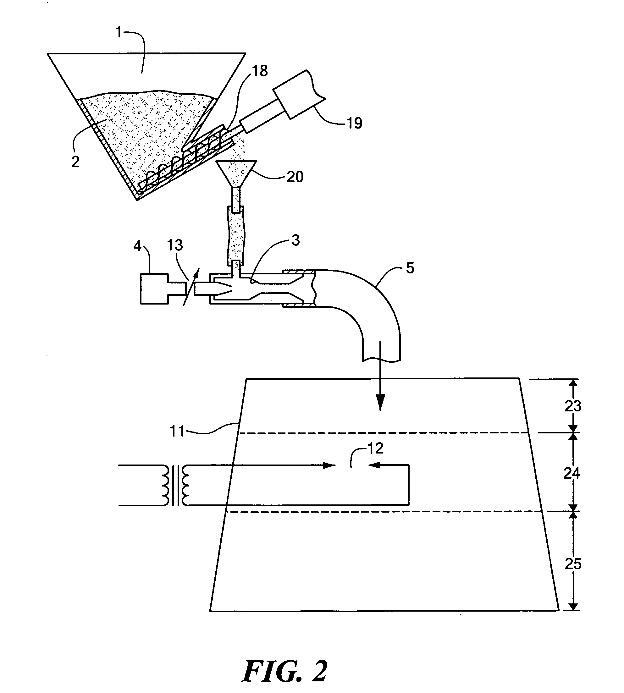
[0023] A process, apparatus and material composition for forming a coherent refractory mass on a surface wherein one or more non-combustible materials are mixed with one or more metallic combustible powders and an oxidizer, igniting the mixture in a combustion chamber so that the combustible metallic particles react in an exothermic manner with the oxidizer and release sufficient heat to form a coherent mass of the material under the action of the heat of combustion, and projecting this mass against the surface so that the mass adheres durably to the surface.

Problems solved by technology

In addition, the rate of deposition of these thermal spraying processes is relatively low and there is a need for higher spray rates.
One of the problems with the present thermal spraying process is the difficulty of controlling the chemical environment and preventing oxidation reactions which can occur on the surface of the powder particles prior to their impingement on the substrate.
The flame spray process is only limited by materials with higher melting temperatures than the flame can provide or if the material decomposes on heating.
Disadvantages of the plasma spray process are its relatively high cost, complexity of the process, slow deposition rate and large amounts of electricity required.
Disadvantages of the electric arc spray process are that only electrically conductive wires can be sprayed and if the substrate requires preheating, a separate heating source is needed.
Porosity is high and cohesive strength is low.
The process is energyefficient: all input energy is used to melt the metal.

Method used


Image

  • Flame spraying process and apparatus
  • Flame spraying process and apparatus
  • Flame spraying process and apparatus

Examples


Embodiment Construction

[0027] The present patent is very similar to co-pending patent application Ser. No. 10 / 774,199 by the same applicant as herein. However, the co-pending patent application is primarily directed to the process of “painting” lines on highways whereas the present application is more generally applicable to flame spraying high temperature ceramic materials onto any surface without the use of external sources of energy.

[0028] The typical non-combustible materials used in the present application are powdered metal oxides such as titanium dioxide, aluminum oxide, silicon dioxide, chromium oxide, magnesium oxide, iron oxide, zirconium oxide, zinc oxide or a mixture of two or more thereof. All of these materials have melting temperatures above the typical oxygen fuel flame temperature and all of them are non-electrically conducting.

[0029] The source of heat is a powdered metallic fuel which is mixed with the powdered non-combustible materials that are to be flame sprayed. The non-combustibl...


PUM

PropertyMeasurementUnit
temperaturesaaaaaaaaaa
flame temperatureaaaaaaaaaa

Abstract

A process, apparatus and material composition for forming a coherent refractory mass on a surface wherein one or more non-combustible materials are mixed with one or more metallic combustible powders and an oxidizer, igniting the mixture in a combustion chamber so that the combustible metallic particles react in an exothermic manner with the oxidizer and release sufficient heat to form a coherent mass of material under the action of the heat of combustion, and projecting this mass against the surface so that the mass adheres durably to the surface.

Description

CROSS REFERENCE TO RELATED APPLICATIONS [0001] This application is related to U.S. patent application Ser. No. 10 / 774,199 filed Feb. 6, 2004 and U.S. patent application Ser. No. 10 / 863,651 filed Jun. 8, 2004, incorporated by reference herein.STATEMENT REGARDING FEDERALLY SPONSORED RESEARCH OR DEVELOPMENT [0002] N / A BACKGROUND OF THE INVENTION [0003] The “flame spray” or “thermal spray” process has been well documented and described in the prior literature. As described in U.S. Pat. No. 6,001,426: “Thermal spraying is a process of applying coatings of high performance materials, such as metal, alloys, ceramics and carbides, onto more easily worked and cheaper base materials. The purpose of the coating is to provide enhanced surface properties to the cheaper bulk material of which the part is made.” As also stated in the same patent: “Thermal spray includes a variety of approaches, but can be grouped into three main coating processes: combustion, wire-arc, and plasma.” Such thermal sp...

Claims


Application Information

Patent Timeline
Patent Type & Authority Applications(United States)
IPC IPC(8): C23C4/00
CPCC23C4/12Y02T50/67C23C4/124C23C4/129Y02T50/60
Inventor LICHTBLAU, GEORGE JAY
Owner GJL PATENTS
Why Eureka
Try Eureka