Coherent laser radar

Inactive Publication Date: 2006-04-06
MITSUBISHI ELECTRIC CORP
View PDF8 Cites 42 Cited by
  • Summary
  • Abstract
  • Description
  • Claims
  • Application Information

AI Technical Summary

Problems solved by technology

However, a laser medium that oscillates at a wavelength of 1.4 μm or longer has difficulty in generating a laser beam with a high efficiency because of a small gain in general.
Also, in the space type laser resonator, the optical parts such as a mirror requires a high precision in the installation, and in the laser radar device that is used outdoors in most cases, the parts are readily out of alignment which arises from a change in temperature, vibrations, or an impact, thereby increasing a loss within the laser resonator.
As a result, there arises such a problem that the output of a transmitted light varies.
In addition, because it is necessary to control the resonator length in order to obtain the transmitted light of a single frequency, a problem occurs in that the single frequency output is not captured while the control is unstable.
Moreover, because the resonator length control is realized by mechanically moving the optical parts within the resonator, there is a problem in that output deterioration arises from the optical parts being out of alignment during the operation.
For that reason, the conventional spatial resonator type coherent laser radar device has difficulty in gaining a reputation for high reliability.
Also, damage occurs in an interior of an optical fiber, an end surface of the optical fiber, an optical part within an inline type optical part, or the like.

Method used


Image

  • Coherent laser radar
  • Coherent laser radar
  • Coherent laser radar

Examples


first embodiment

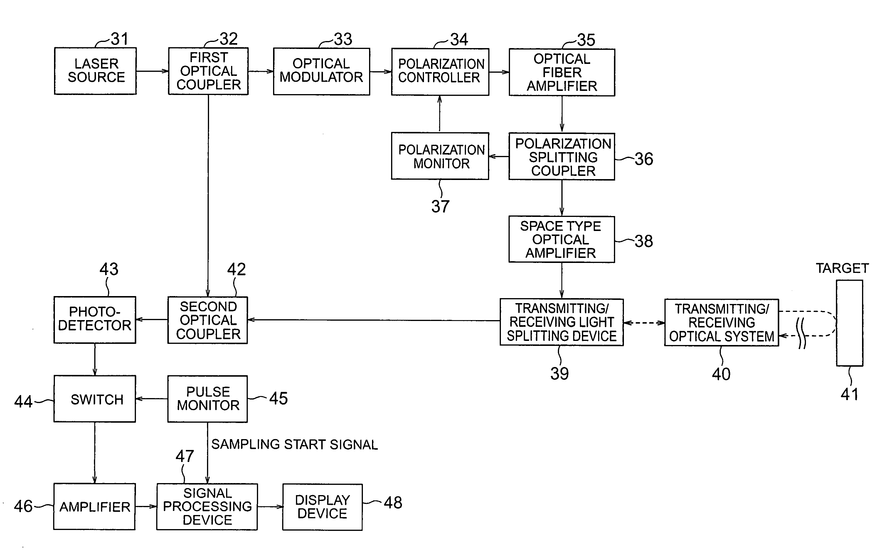
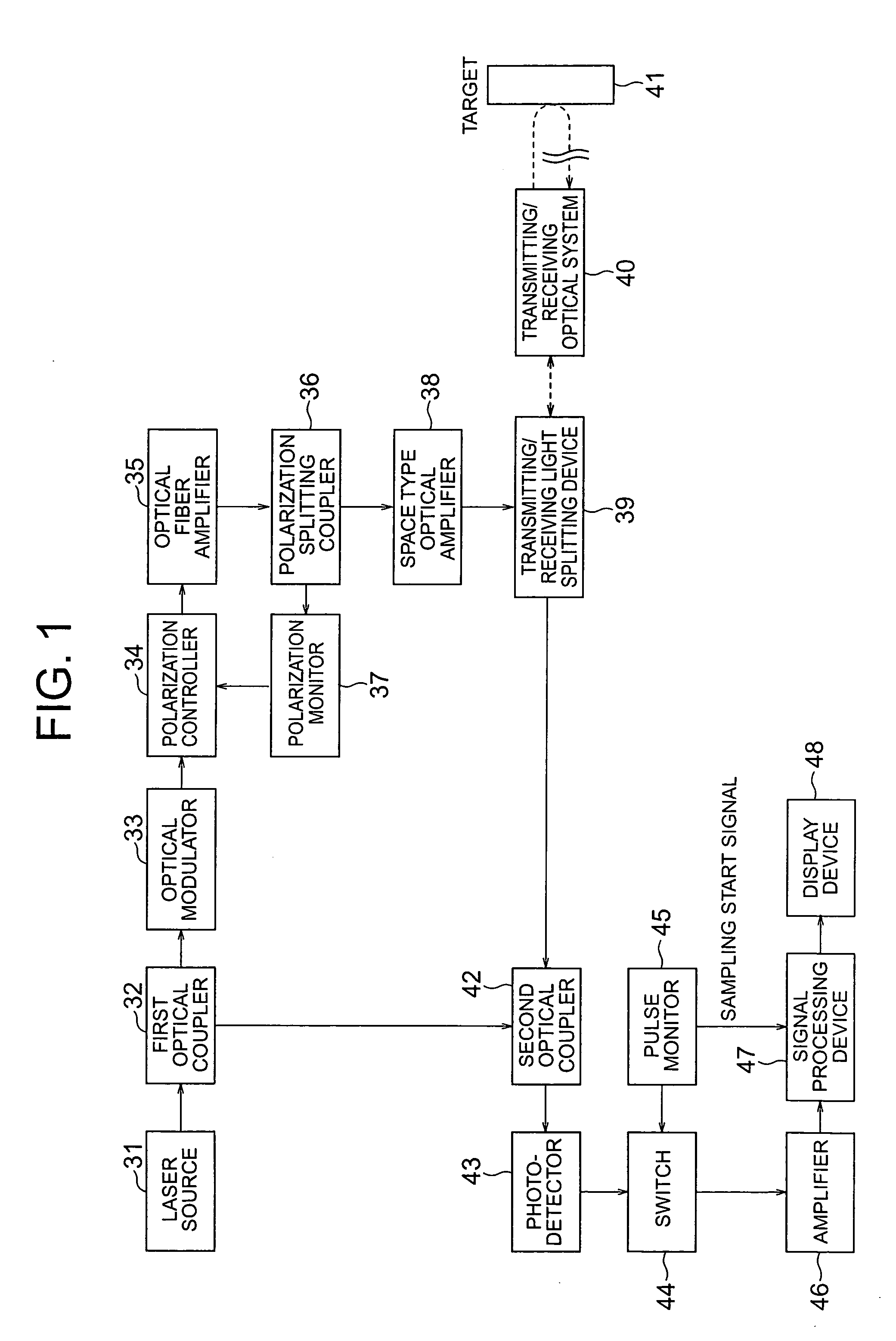
[0036]FIG. 1 is a block diagram showing the structure of an optical fiber type coherent laser radar device according to a first embodiment of the present invention. The optical fiber type coherent laser radar device shown in FIG. 1 includes a laser source 31 that oscillates a laser beam that has been linearly polarized, a first optical coupler 32 that divides the laser beam from the laser source 31 into two lights, a local light and a transmitted light, an optical modulator 33 that modulates the transmitted light from the first optical coupler 32, a polarization controller 34 that adjusts the polarization of the transmitted light that has been outputted from the optical modulator 33 on the basis of a polarization monitor output, an optical fiber amplifier 35 that amplifies the transmitted light that has been outputted from the polarization controller 34, a polarization splitting coupler 36 that splits the transmitted light that has been outputted from the optical fiber amplifier 35 ...

second embodiment

[0059]FIG. 3 is a block diagram showing the structure of a space type optical amplifier by using an OPA (Optical Parametric Amplification) according to a second embodiment of the present invention. As shown in FIG. 3, the space type optical amplifier 38 includes a collimating optical system 61, an pumping light source 62 that outputs a pulsed pumping light, a dichroic mirror 63 that couples the transmitted light with the pumping light, a first nonlinear material 64 that converts a power of the pumping light into a power of the transmitted light due to the nonlinear effect, a first splitting mirror 65 that reflects an idler light that has been generated in OPA and transmits the transmitted light and the pumping light, a second nonlinear material 66 that converts the power of the pumping light into the power of the transmitted light due to the nonlinear effect, and a second splitting mirror 67 that reflects the idler light and the pumping light and transmits only the transmitted light...

third embodiment

[0073] In OPA, the pumping light and the transmitted light are pulses, and as shown in FIG. 5, only when the pumping light (refer to FIG. 5(b)) and the transmitted light (refer to FIG. 5(a)) are superimposed in terms of time on each other within crystal, the transmitted light is amplified (refer to FIG. 5(c)). Because the transmitted light pulses the laser source of a CW output by the optical modulator, a variation (pulse jitter) of the timing of the pulse depends on the electric circuit. On the other hand, in the case where a solid state laser is used for the pumping light source, and the Q switch operation is conducted, a large pulse jitter occurs as compared with the transmitted light which is attributable to a change in the temperature environments or the exciting state. Accordingly, when the transmitted light and the pumping light are made identical in the pulse width with each other, the gain may be deteriorated or the transmitted light may not be amplified at all due to the s...


PUM


Abstract

To obtain a coherent laser radar device that realizes high reliability and the high output of a transmitted light, the device includes a first optical coupler that branches a laser beam from a laser source into two lights, a local light and a transmitted light, an optical modulator that modulates the transmitted light, a space type optical amplifier that amplifies the modulated transmitted light, a transmitting / receiving optical system that applies the amplified transmitted light toward a target and receives a scattered light from the target, a transmitting / receiving light splitting device that splits the transmitted light and the received light, a second optical coupler that mixes the local light and the split received light together, a photodetector that detects heterodyne of a mixed light, a beat signal amplifier that amplifies a detected signal, a signal processing device that processes an amplified signal, and a display device that displays a processed result. The first and second optical couplers and an optical modulator are structured by polarization maintained type optical elements, and an optical path that extends from the laser source to the space type optical amplifier through the first optical coupler, an optical path that extends from the transmitting / receiving light splitting device to the photodetector through the second optical coupler, and an optical path that extends from the first optical coupler to the second optical coupler are connected by polarization maintained type single mode optical fibers.

Description

TECHNICAL FIELD [0001] The present invention relates to a coherent laser radar device, and more particularly to an optical fiber type coherent laser radar device in which optical parts are connected to each other by optical fibers for the purpose of measuring physical information such as a distance to a target, a velocity, a density distribution, or a velocity distribution. BACKGROUND ART [0002] A laser radar applies a laser beam onto a target (atmospheric air, fine grains or aerosols in the atmospheric air, constructs, or the like) from a remote place and receives a reflected light (scattered light) from the target, thereby making it possible to measure diverse information such as fine grains in the atmospheric air, the distribution of molecules, the velocity of wind, or a distance to a construction, from the remote place. [0003] In most cases, the laser radar is employed outdoors, and requires a high reliability. Also, in order to measure information that pertains to a remote plac...

Claims


Application Information

Patent Timeline
IPC IPC(8): G01S13/00G01S7/48G01S7/481G01S7/484G01S7/499
CPCG01S7/48G01S7/481G01S7/4811G01S7/4813G01S7/4818G01S7/484G01S7/499G01S17/06G01S17/95G02F1/39Y02A90/10
Inventor YANAGISAWA, YAKAYUKIYAMAMOTO, SYUHEIHIRANO, YOSHIHITOKAMEYAMA, SHUMPEIANDO, TOSHIYUKI
Owner MITSUBISHI ELECTRIC CORP
Why Eureka
Try Eureka