
Novel stationary phases for use in high-performance liquid chromatography

a technology of stationary phase and liquid chromatography, which is applied in the direction of ion exchangers, separation processes, filtration separation, etc., can solve the problems of irreversible adsorption of some analytes, excessive peak tailing, and increased retention, so as to reduce surface silanol activity and reduce peak trailing

Inactive Publication Date: 2006-04-13
AGILENT TECH INC
View PDF15 Cites 7 Cited by
  • Summary
  • Abstract
  • Description
  • Claims
  • Application Information

AI Technical Summary

Benefits of technology

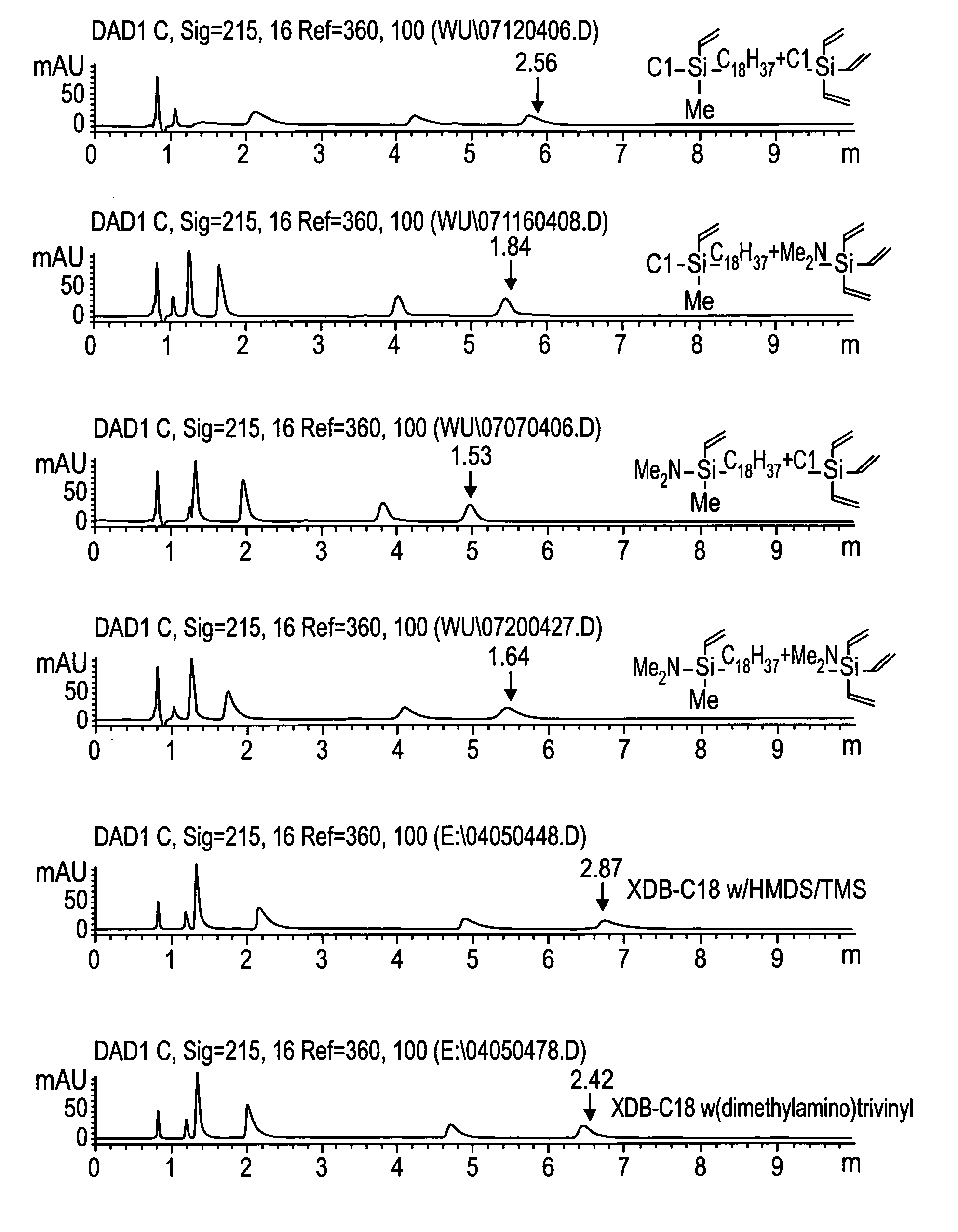
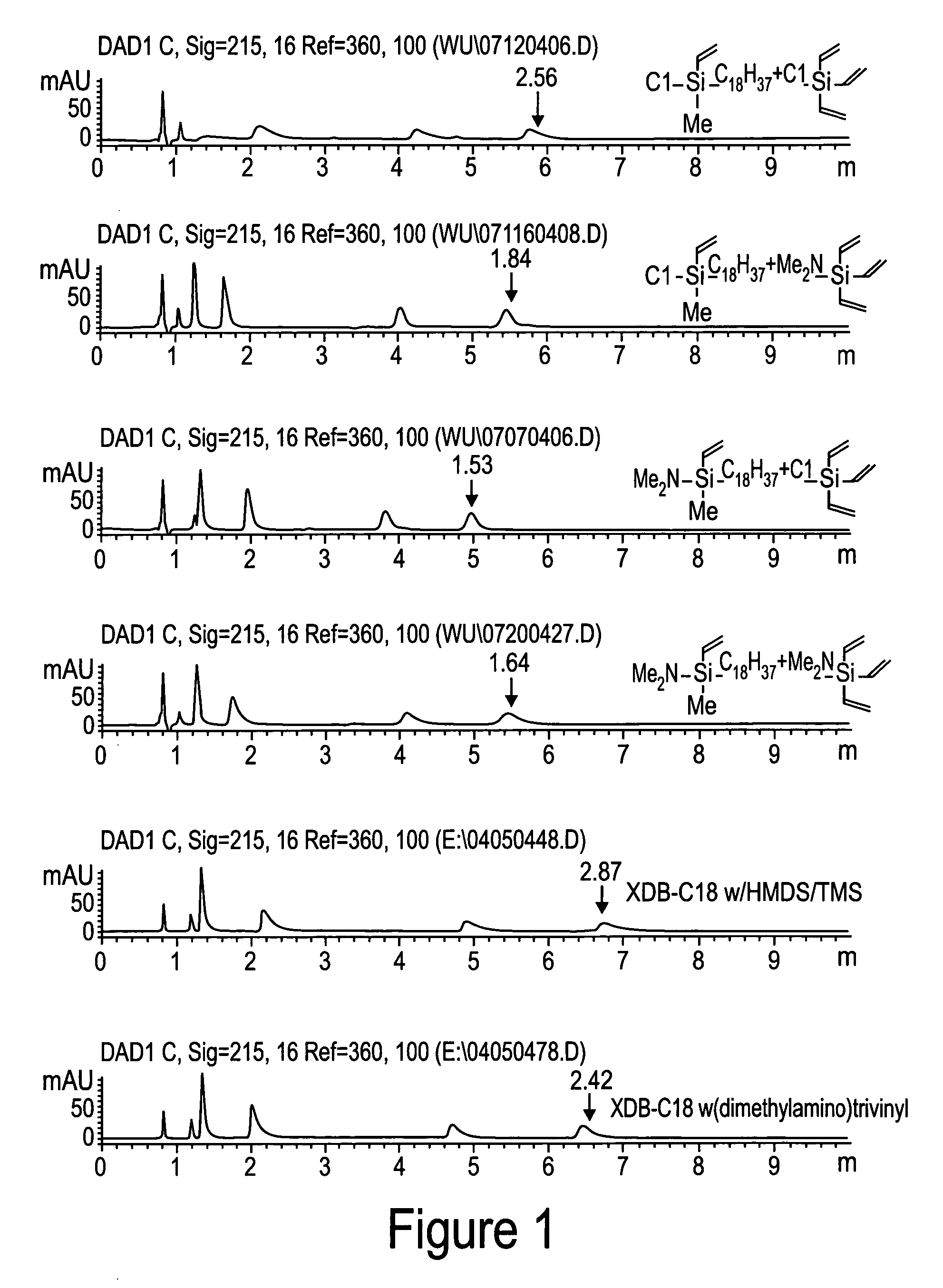
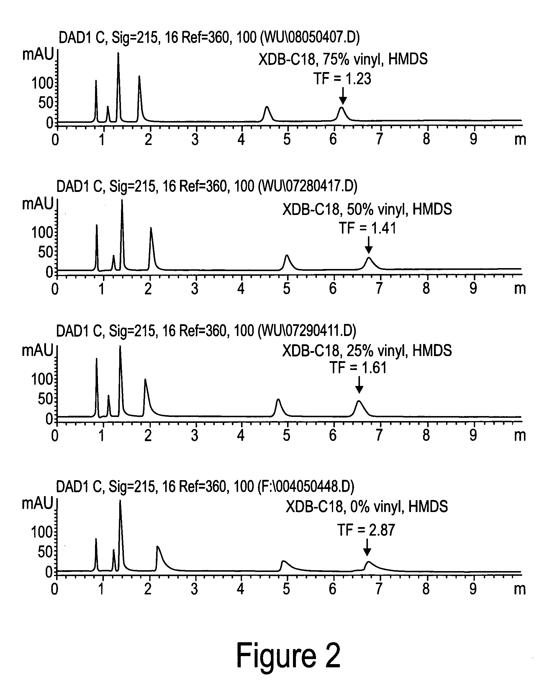
[0013] In one embodiment, the invention provides a stationary phase for use in chromatography having side groups comprising one or more unsaturated groups such as vinyl, allyl, ethynyl, propynyl as side groups. In another embodiment, the invention provides a method for neutralizing reactive silanols using endcapping reagents comprising one or more unsaturated groups such as vinyl, allyl, ethynyl, propynyl, and the like. In one aspect, stationary phases according to the invention comprise a hydrophobic layer. In another aspect, the stationary phases comprise reduced surface silanol activity, which may result in reduced peak trailing during separation of compounds.

Problems solved by technology

This secondary interaction between analytes and residual silanol groups create problems, including increased retention, excessive peak tailing, especially at mid pH range for basic compounds, and irreversible adsorption of some analytes.
In practice, none of these approaches is totally satisfactory.
However, polymeric phases usually have poor mass transfer and poor reproducibility.
Finally, the high temperature of silylation in a seal ampoule is not practical and difficult to perform commercially compared with the traditional liquid phase endcapping procedure.
For example, the hydrolyzed amide phase leaves aminopropyl moieties on the surface, and can strongly adsorb acidic and polar compounds, causing peak tailing or missing.

Method used


Image

  • Novel stationary phases for use in high-performance liquid chromatography
  • Novel stationary phases for use in high-performance liquid chromatography
  • Novel stationary phases for use in high-performance liquid chromatography

Examples


example 1

Preparation of chloromethylvinyloctadecylsilane

[0031] Organosilanes were purchased from Gelest, Inc. Morrisville, Pa. and solvents and other chemicals were purchased from Aldrich, Milwaukee, Wis., unless specifically notified.

[0032] To a solution of dichloromethylvinylsilane (112.8 g, 0.8 mol) in THF (300 ml) / hexane (500 ml) was added octadecylmagnesium chloride in THF (800 ml, 0.5 M) dropwise at room temperature. After addition, the mixture was stirred at room temperature overnight. The solvent was removed by distillation. To residue was added hexane (500 ml). The white solid was filtered, and washed with hexane (400 ml×3) under argon. The solvent was removed by distillation. The residue was distilled out under vacuum (at 180-190° C. / 0.05 mm Hg) to yield the desired product, 63.32 g, yield 44.2%.

example 2

Preparation of (dimethylamino)methylvinyloctadecylsilane

[0033] A four-neck flask was equipped with a mechanic stirrer, two dry-ice condensers. Nitrogen was purge gently through one dry-ice condenser and out from other condenser. Chloromethylvinyloctadecylsilane (63.32 g, 0.175 mole) and hexane (100 ml) were added into the flask. Dimethylamine gas was purged into the system through a dry-ice condenser and was dropped into the mixture. The white precipitate was formed. The reaction was followed by using GC. Dimethylamine and continuing to purge until the peak of chloromethylvinyloctadecylsilane disappeared on GC. The precipitate was filtered and washed with hexane (400 ml×3) under argon. Hexane was removed by distillation. The residue was distilled under vacuum (at 210° C. / 0.06 mm Hg) to yield the desired product, 61.22 g, yield 94.8%.

example 3

Preparation of (dimethylamino)trivinylsilane

[0034] (Dimethylamino)trivinylsilane was obtained by the same method as Example 2. A four-neck flask was equipped with a mechanic stirrer, two dry-ice condensers. Nitrogen was purge gently through one dry-ice condenser and out from other condenser. Chlorotrivinylsilane (103 g, 0.713 mole) and hexane (100 ml) were added into the flask. Dimethylamine gas was purged into the system through a dry-ice condenser and was dropped into the mixture. The white precipitate was formed. The reaction was followed by using GC. Dimethylamine was continued to purge until the peak of chlorotrivinylsilane disappeared on GC. The precipitate was filtered and washed with hexane (400 ml×3). Hexane was removed by distillation. The residue was distilled under vacuum (at 22° C. / 0.4 mm Hg) to yield the desired product, 74 g, yield 68%.


PUM

PropertyMeasurementUnit
Molar densityaaaaaaaaaa
Hydrophilicityaaaaaaaaaa
Hydrophobicityaaaaaaaaaa

Abstract

The invention provides novel materials for chromatography and chromatography columns. The invention provides a monofunctional silane or a mixture of two or three monofunctional silanes chemically bonded to a substrate, at least one monofunctional silane having at least one unsaturated hydrocarbon group, R′, covalently attached to the substrate, containing the silane structure is of form: Where R′ is independently selected from the group consisting of alkenyl, alkynyl, and phenyl, R″ is selected from the group consisting of alkyl, substitute alkyl, alkenyl, substitute alkenyl, alkynyl, and aryl, substitute aryl, R is selected from the group consisting of alkyl, substitute alkyl, alkenyl, substitute alkenyl, alkynyl, and aryl, substitute aryl, alkylamine, amide, ether, alcohol, carbamate, ester, an anion exchanger, and a cation exchange. Methods for manufacture and design of the columns are also provided and disclosed.

Description

RELATED CASE [0001] This application claims priority under 35 U.S.C. § 120 to U.S. patent application Ser. No. 10 / 837,265, filed Apr. 30, 2004, the entirety of which is incorporated by reference herein.FIELD OF THE INVENTION [0002] This invention relates to materials for use in chromatography, and the processes for manufacturing the materials. In particular, the invention relates to packing materials for columns for liquid chromatography. BACKGROUND OF THE INVENTION [0003] Silica particles are by far the most widely used supports for reversed-phase liquid chromatography stationary phases. The high mechanical stability, monodisperse particles, high surface area, and easily tailored pore size distributions make silica superior to other supports in terms of efficiency, rigidity, and performance. Silica bonding chemistry is also allows for a wide variety of stationary phases with different selectivies to be made on silica [1, 2, 3]. [0004] Silanes are the most commonly used surface modi...

Claims


Application Information

Patent Timeline
IPC IPC(8): B01D15/08
CPCB01D15/3804B01J20/286B01J20/287B01J20/3227B01J20/3242B01J39/26B01J41/20
Inventor CHEN, WU
Owner AGILENT TECH INC
Learn More