Charged particle beam apparatus

a particle beam and charge technology, applied in the field of scanning electron microscope, can solve the problems of difficult to obtain a high-resolution high-sensitivity image for observation, and difficulty in providing compact sem apparatus designed for stereoscopic observation, and achieve the effect of high functionality

Inactive Publication Date: 2006-04-13
HITACHI HIGH-TECH CORP
View PDF14 Cites 61 Cited by
  • Summary
  • Abstract
  • Description
  • Claims
  • Application Information

AI Technical Summary

Benefits of technology

[0009] The present invention realizes a subminiature, high-sensitivity, high-resolution SEM incorporating a pump and a secondary electron detector. Furthermore, the invention makes it possible to provide highly functional SEM apparatuses based on electron beams, such as a subminiature SEM apparatus for 3D observation and a movable-column type or multicolumn type SEM apparatus.

Problems solved by technology

The known technology has a problem in that it is difficult to obtain a high-resolution high-sensitivity image for observation with an SEM apparatus having a secondary electron detector and an electron source housed in a small housing.
Also, there is difficulty in providing a compact SEM apparatus that is designed for stereoscopic observation.

Method used


Image

  • Charged particle beam apparatus
  • Charged particle beam apparatus
  • Charged particle beam apparatus

Examples


first embodiment

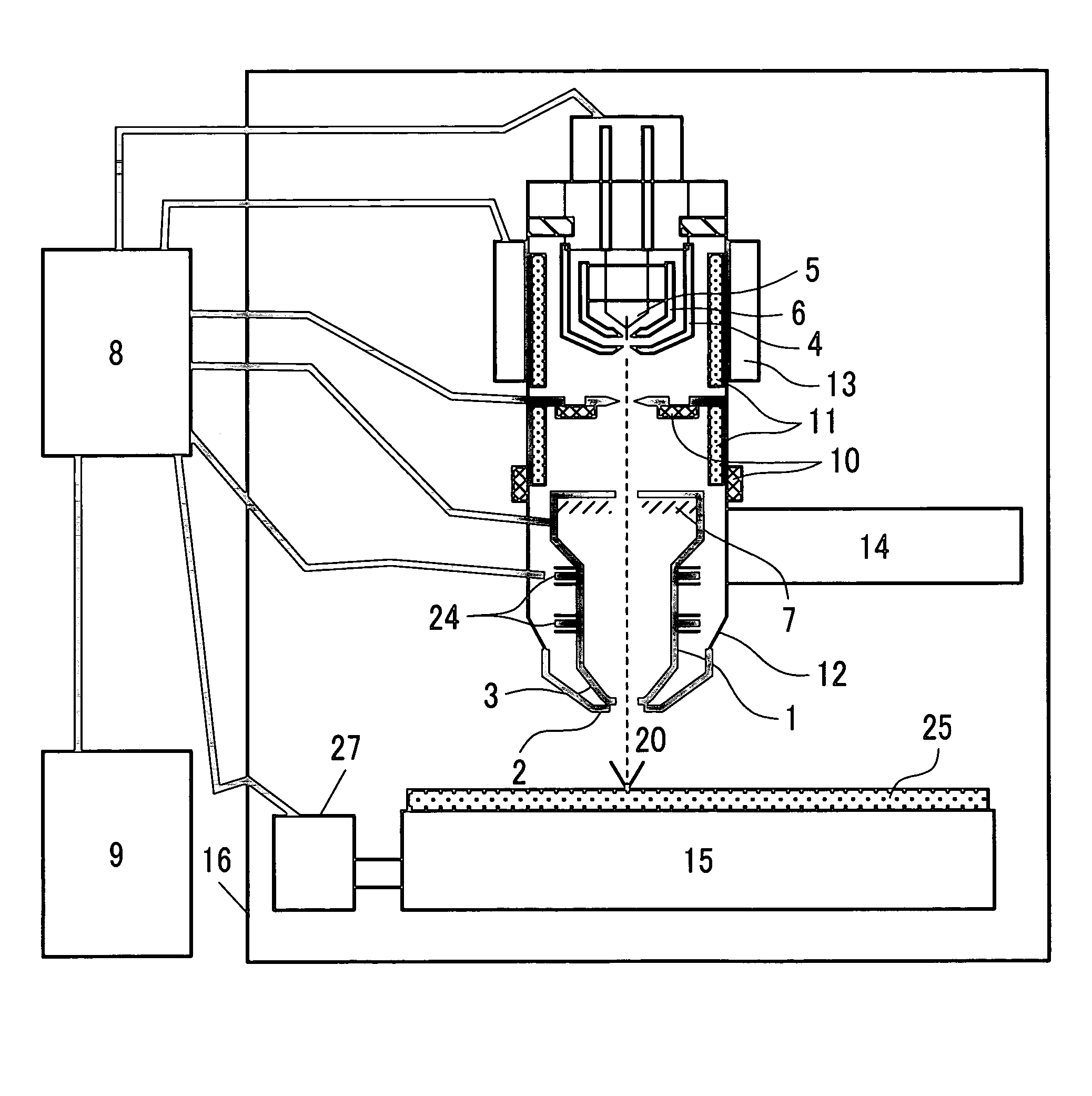
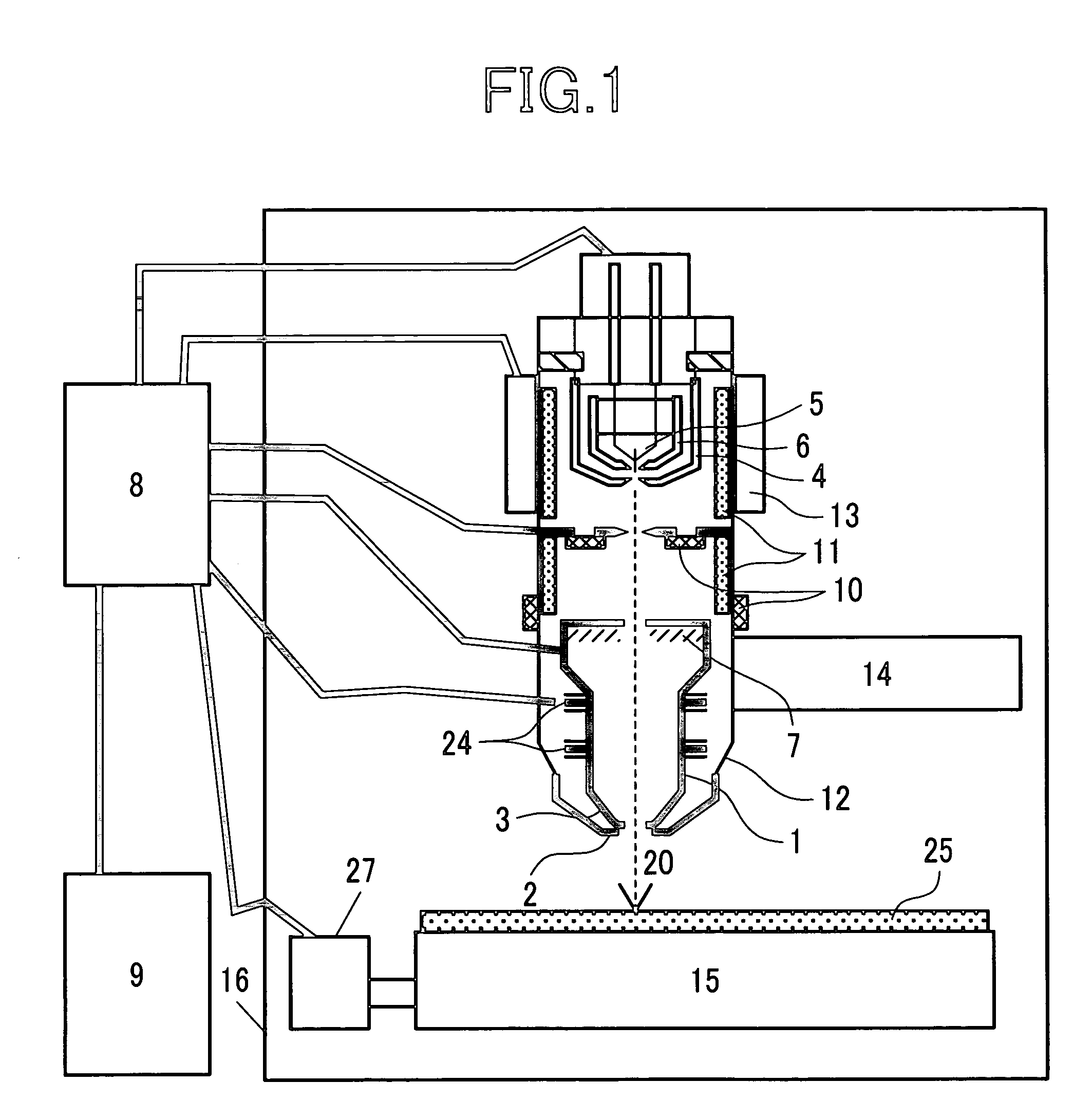
[0027]FIG. 1 schematically shows an embodiment of the present invention.

[0028] An electron source 5, such as a Schottky electron source, which is made of Zr / O / W, heated to 1600-1800 K, a suppressor electrode 6 and an extraction electrode 4 constitute an electron gun, which produces an electron beam probe 20 in the form of an electron beam. When the electron beam probe 20 impinges on a sample substrate 25, it is focused by an electrostatic objective lens, consisting of an objective lens inner electrode 3 located on the electron source side, and an objective lens sample side electrode 2 located on the sample side, so that it becomes a minute electron beam probe with a diameter of 30 nm to 2 nm. This beam is scanned in the x and y directions by a deflector 24, and released secondary electrons or backscattered electrons are detected by an electron detector 7 and converted into electrical signals, which signals are then processed by a controller 8, so that an SEM image appears on a disp...

second embodiment

[0054]FIG. 10 schematically shows a second embodiment of the present invention.

[0055] This embodiment concerns an inspection device for a mold 100 for use in the nano-in-print process as a means for formation of nanopatterns on substrates, to which the present invention is applied. The nano-in-print process is a process whereby nanopatterns are formed as follows: a thin coating of thermally or optically curable resin is formed on a Si, plastic or glass substrate; a mold is pressed against it to shape it; the resin is cured by heat or ultraviolet rays; then the mold is released. Because ultraviolet rays may be used and thermal expansion or plastic deformation is undesirable, the mold is made of glass or quartz. For this process, the 3D structure of the mold is important for the sake of mold releasability and pattern accuracy. The object size range for optical inspection, such as with a confocal microscope, is too small to measure this mold. On the other hand, the use of a convention...

third embodiment

[0069]FIG. 13 shows an example of a focused ion beam system operating as a process unit, to which the present invention is applied. An ion beam probe 132, generated by an ion source 130, is focused by an electrostatic lens in an ion beam column 131 at an acceleration velocity of 10 to 30 kV, and it is cast on a sample substrate 25, whereby a desired area is cut by ion beam etching. In this system, an SEM column 101 according to the present invention, which is tilted at an angle ω, can be moved by transport means 14 to vary the working distance WD. When the working distance WD is between 5 mm and 10 mm, a wider area can be observed though the resolution is low, and staining due to sample element redeposition is reduced. Therefore, the SEM is used as a monitor during radiation of an ion beam and to detect an end point. It is also used to get an overall view of a sample area. On the other hand, when the working distance WD is shorter, specifically between 1 mm and 5 mm, observation wit...


PUM


Abstract

A charged particle beam apparatus in which an electrostatic lens is used as a main focusing element to obtain a subminiature high-sensitivity high-resolution SEM, a drift tube for an electron beam is located inside a column between an electron source and a sample, and a detector for secondary electrons is located inside the drift tube. This solves the problem associated with the provision of a secondary electron detector, which heretofore has been a bottleneck in making a subminiature high-resolution SEM column.

Description

CLAIM OF PRIORITY [0001] The present application claims priority from Japanese application JP 2004-297117, filed on Oct. 12, 2004, the content of which is hereby incorporated by reference into this application. FIELD OF THE INVENTION [0002] The present invention relates in general to a scanning electron microscope (SEM) of the type which is used to observe microstructures typically using an electron beam; and, more particularly, the invention relates to a compact high-sensitivity high-resolution SEM and an electron beam applied apparatus, which are capable of implementing various sample observation functions. BACKGROUND OF THE INVENTION [0003] As an example of a compact high-resolution SEM, reference is made to FIG. 1 in JP-B No. 1681 / 1995. This compact high-resolution SEM is characterized by the fact that an electrostatic lens is provided for focusing electrons into an electron beam, where an electrode outside an objective lens is 0 V and a positive high voltage is applied inside t...

Claims


Application Information

Patent Timeline
Patent Type & Authority Applications(United States)
IPC IPC(8): G21K7/00
CPCH01J37/244H01J37/28H01J2237/0268H01J2237/04756H01J2237/1205H01J2237/121H01J2237/188H01J2237/24465H01J2237/2611H01J2237/31749
Inventor OHSHIMA, TAKASHISATO, MITSUGUKATAGIRI, SOICHI
Owner HITACHI HIGH-TECH CORP
Why Eureka
Try Eureka