Minimally invasive pedicle screw and guide support

a technology of guide support and pedicle screw, which is applied in the field of minimally invasive pedicle screw and tubular installation support, can solve the problems of increasing the operating time and x-ray exposure of both the surgeon and the patient, prolonging the healing time of the patient, and complicated procedures, so as to minimize the cost of the procedure and quick healing

Inactive Publication Date: 2006-04-13
WONG DAVID A
View PDF0 Cites 155 Cited by
  • Summary
  • Abstract
  • Description
  • Claims
  • Application Information

AI Technical Summary

Benefits of technology

[0031] The pedicle screw as described herein is intended to provide an anchor for instrumentation that can be used to interconnect the stem portion of a plurality of pedicle screws provided in the vertebrae of a patient's spine. The instrumentation can include rods having various lengths which are attached to the stem portion of the screws for stabilizing and fixating the vertebrae of the spine of the patient which will allow the spine to quickly heal without the tissue trauma normally encountered with extensive percutaneous spinal surgery. The use of the support sleeve in conjunction with the installation of the pedicle screw is critical in that the screw is firmly held within the sleeve as the sleeve is inserted through a small incision in the skin over the pedicle portion of the vertebrae so that the soft tissue and muscle is not further damaged by the threads of the screw during rotation and insertion of the pedicle screw and the screw remains properly aligned.
[0032] The support sleeve can be reused for the insertion and withdrawal of any number of pedicle screws during the surgical process which minimizes the cost of this procedure as well as providing minimally invasive insertion of the pedicle anchor screws required for the stabilization and healing of the patient's spine.
[0033] The support sleeve in conjunction with the shaft of the drive tool used for driving the screw can incorporate indices or marks

Problems solved by technology

This process in turn had an inherent risk of re-fracturing the spinal fusion potentially prolonging the healing time for the patient.
One of the major problems in immobilizing the spine to facilitate the healing process has been the complicated procedure for insertion and anchoring of the support screws in the pedicle.
This methodology had many inherent problems since it had a number of intricate steps and the need for accurate placement of each element during these steps increased the operating time and x-ray exposure for both the surgeon as well as the patient.
At times, exit penetration of the vertebrae by an element into the abdomen or nerve canal of the patient produced catastrophic results.
This type of incision caused considerable problems from the standpoint that the length of the incision is relatively long in order to allow access by the surgeon into the required vertebrae area.
This standard incision resulted in extensive time required for patient healing as well as problems encountered with scar tissue.
The guide wire is sometimes difficult to place and mane

Method used


Image

  • Minimally invasive pedicle screw and guide support
  • Minimally invasive pedicle screw and guide support
  • Minimally invasive pedicle screw and guide support

Examples


Embodiment Construction

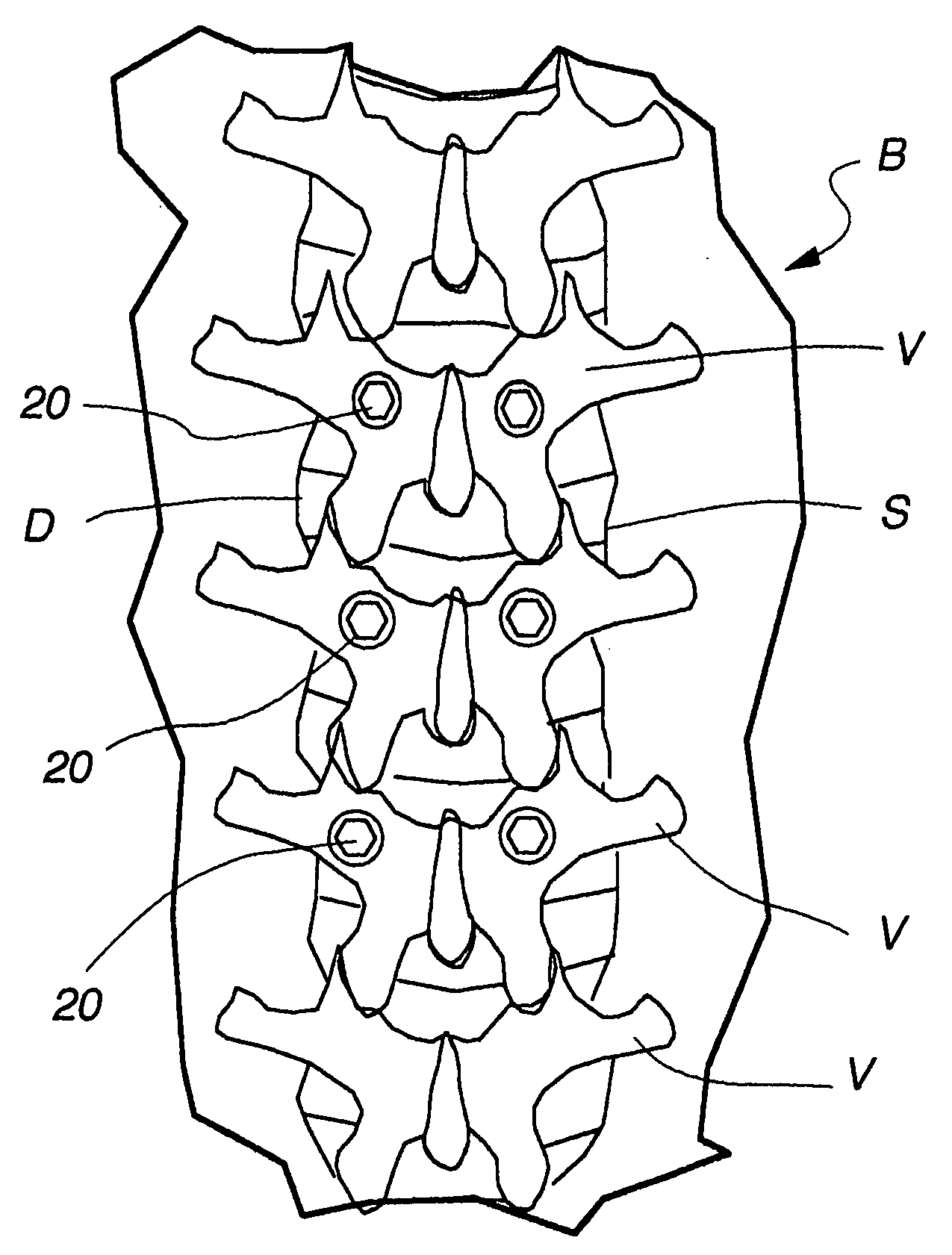
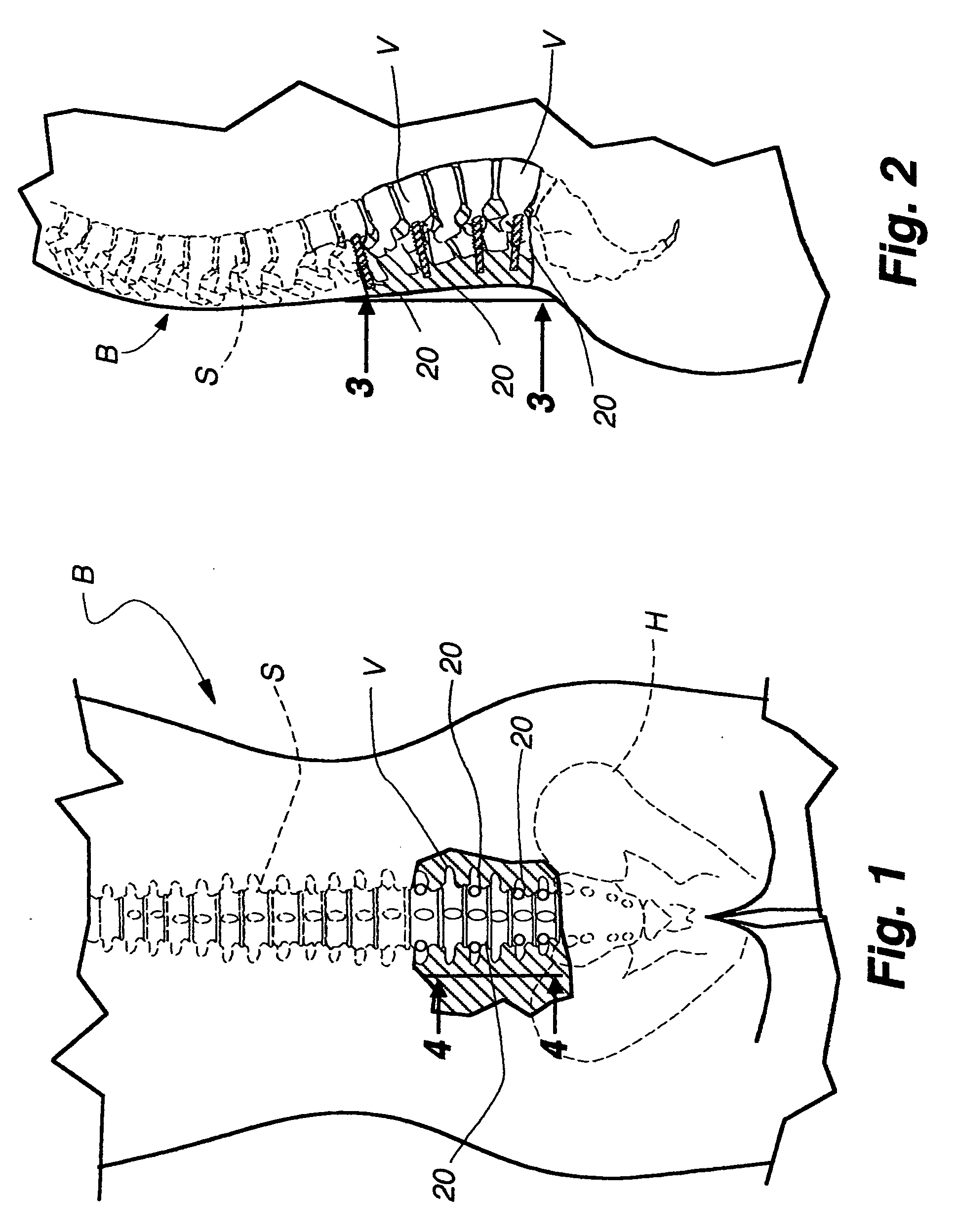
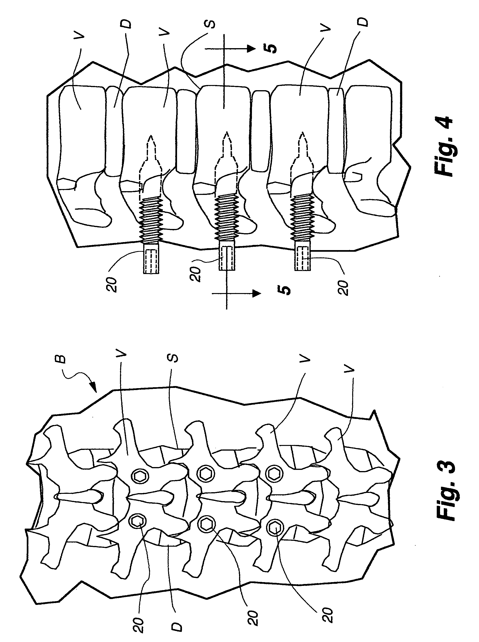
[0061] Turning now more specifically to the drawings, FIGS. 1-5 show a partial pictorial view of a patient's body B revealing the position of the spinal column S, the pelvis bone H as well as the individual vertebrae V which makes up a portion of the spine. Intervertebral discs D which are positioned between each of the vertebrae V go together to protect and support the spinal cord and nerves C positioned within the structure making up the spinal column S.

[0062] In each of the views is seen a pedicle or orthopedic screw 20 which has been strategically positioned and installed within the pedicle portion of certain vertebrae V. The primary purpose of the pedicle screw 20 is to provide a rigid anchor in the affected and adjacent vertebrae so that the vertebrae can be rigidly supported within the spinal column S to stabilize the vertebrae V to allow the fusion of fractured vertebrae as well as to allow healing of damaged or ruptured discs D that may be present in the spinal column S. I...


PUM


Abstract

A minimally invasive orthopedic bone attachment system comprising a pedicle screw and guide support sleeve for insertion of the screw. The pedicle screw is a self-boring, self-tapping integral screw having a distal sharply pointed end for guiding the insertion of the screw as well as forming a borehole for the self-tapping threads of the screw. The proximal end of the screw provides a cylindrical extension which can include a recess for receiving a rotational drive tool or wrench. The length of the threads and the type of threads provided in the screw are designed for the type of orthopedic surgery that is intended. A relatively thin hollow support sleeve including an internal threaded section in the distal end is provided to match the threads and the length of the threaded portion of the pedicle screw. The proximal end of the sleeve includes a central passageway having an internal diameter that can receive the extension portion of the screw and also guide and receive a drive device for the screw. A retainer clip associated with circumferential slots spacedly indexed along the longitudinal surface of the drive device can be used to limit the depth of the screw upon insertion as well as to lock the drive device as an assembly with the screw and sleeve to form the attachment system. A small diameter passageway can be provided along the longitudinal axis of the assembly extending from the proximal end of the drive device through the screw to exit through the pointed distal end of the screw. A thin rigid rod having a point at the distal end is slidably positioned within the narrow passageway. The proximal end of the road includes a cap. A flange surface on the under portion of the cap limits the travel of the rod through the assembly. The length of the rod is determined so that it equals the length of the assembly plus an additional dimension corresponding to the anticipated installed depth of the screw. Prior to insertion of the screw, the rod is driven into the bone through the assembly. The location of the rod is ascertained by an image guidance system to determine the correct final projected location of the screw upon installation.

Description

RELATED APPLICATIONS [0001] This application claims the benefit of U.S. Provisional Patent Application Ser. No. 60 / 617,109 filed Oct. 8, 2004.BACKGROUND OF THE INVENTION [0002] 1. Field of the Invention [0003] This invention is directed to an improved pedicle screw and a tubular installation support for spinal stabilization surgery. It is more specifically directed to a threaded screw having a smooth cylindrical barrel at the proximal end and a smooth, narrow pointed distal end. A hollow cylindrical sleeve having interior threads is mated with the screw to support the screw and hold it in alignment during installation. [0004] 2. Discussion of the Background [0005] Over the years a number of various types of threaded fasteners have been used in orthopedic surgery to hold bone fragments as well as to reattach ligaments and soft tissue to a bone section. As a result, many innovations have been provided to assist or aid in the installation of the screws into the bone as well as providin...

Claims


Application Information

Patent Timeline
IPC IPC(8): A61B17/58
CPCA61B17/1735A61B17/8605A61B17/8635A61B17/864A61B17/8891A61B2019/304A61B17/1757A61B2090/034
Inventor WONG, DAVID A.
Owner WONG DAVID A
Why Eureka
Try Eureka