Hydrogen generator and fuel cell system

a fuel cell and hydrogen generator technology, applied in the direction of sustainable manufacturing/processing, process and machine control, instruments, etc., can solve the problems of increasing the possibility of degrading the catalytic activity, increasing the possibility of reducing the catalytic activity of the reforming catalyst, and not yet developing the general infrastructure of the hydrogen gas supply system, so as to achieve good hydrogen production stably and prevent the effect of the catalytic activity decreas

Active Publication Date: 2006-04-20
PANASONIC CORP
View PDF4 Cites 29 Cited by
  • Summary
  • Abstract
  • Description
  • Claims
  • Application Information

AI Technical Summary

Benefits of technology

[0011] The present invention solves the foregoing and other problems, and it is an object of the invention to provide a hydrogen generator that prevents decrease in the catalytic activit

Problems solved by technology

At present, a hydrogen gas supply system has not yet been developed as a general infrastructure.
With such hydrogen generators, when the hydrogen generator is repeatedly operated and stopped, the oxidization and reduction of the catalyst is more likely to be repeated at high temperatures than when the hydrogen generator is continuously operated, increasing the possibility of degrading the catalytic activity.
As described above, temperature conditions of the hydrogen generator at the stop vary depending on the operation conditions that precede the stop, but the above-described conventional internal gas replacement

Method used


Image

  • Hydrogen generator and fuel cell system
  • Hydrogen generator and fuel cell system
  • Hydrogen generator and fuel cell system

Examples


embodiment 1

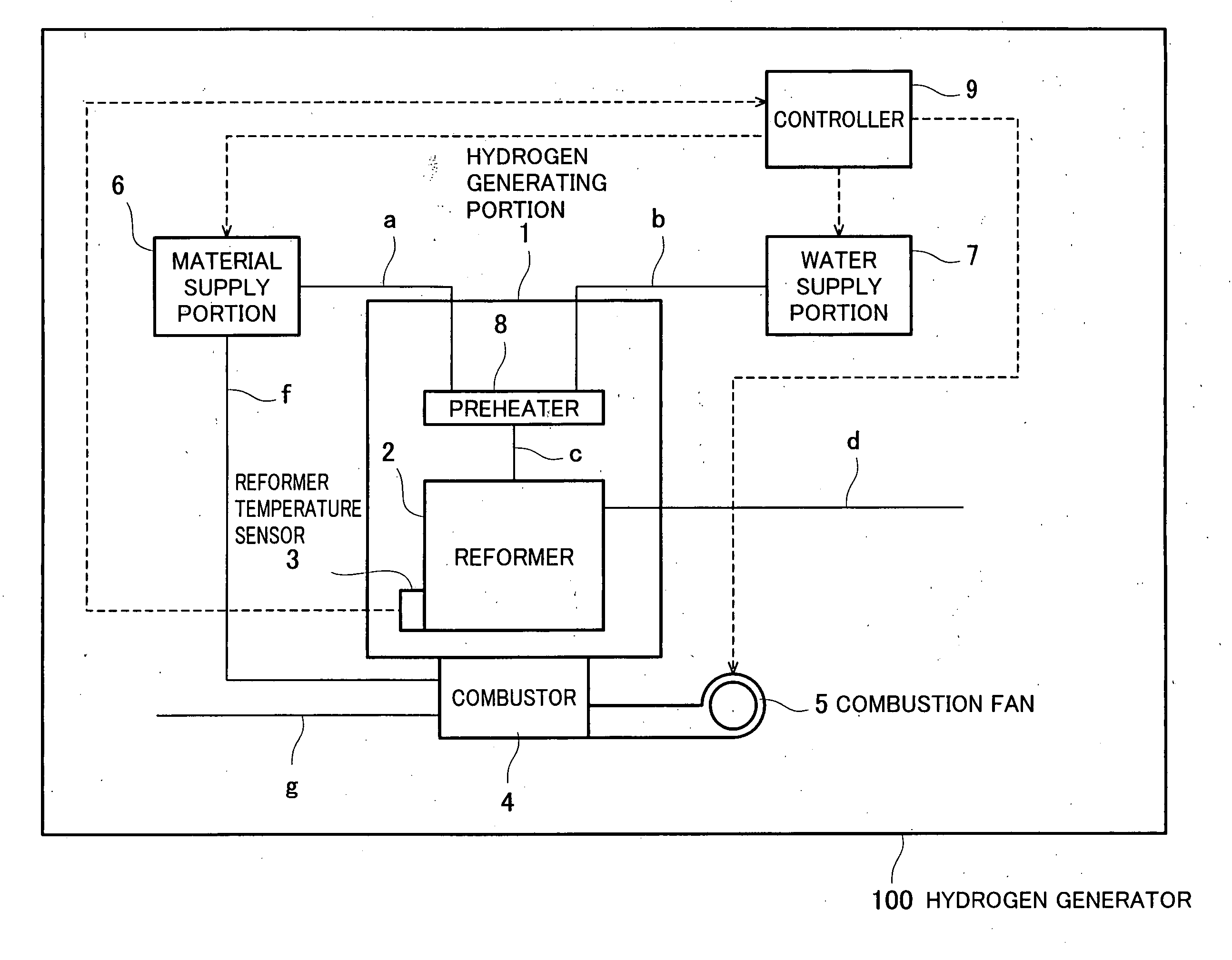
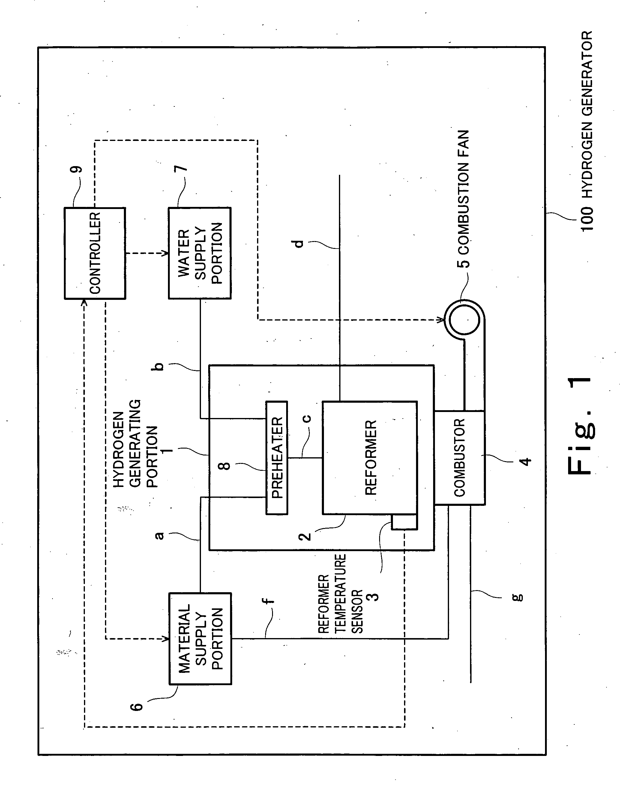
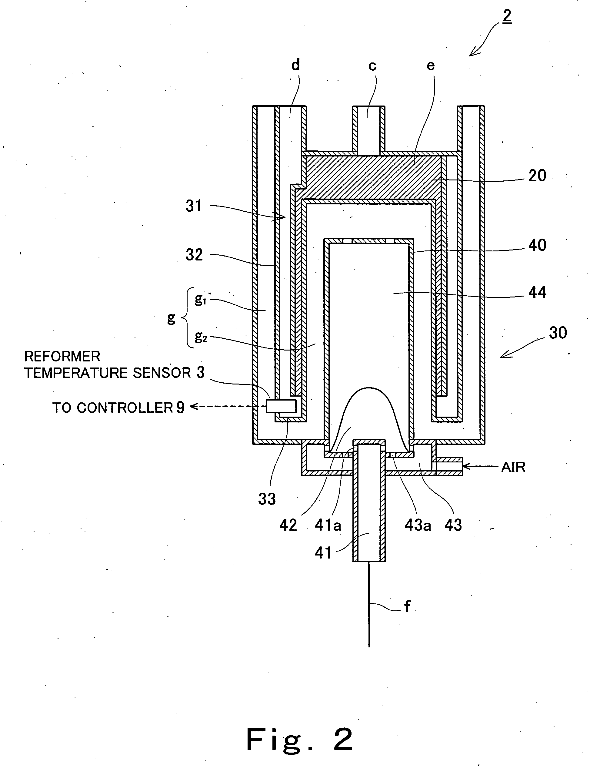
[0047]FIG. 1 is a block diagram schematically showing the configuration of a hydrogen generator according to Embodiment 1 of the invention. FIG. 2 is a cross-sectional view schematically showing the configuration of the reformer shown in FIG. 1. FIG. 3 is a block diagram schematically showing the configuration of the controller shown in FIG. 1.

[0048] As shown in FIG. 1, a hydrogen generator 100 comprises, as its main constitutional elements, a hydrogen generating portion 1 having a preheater 8 and a reformer 2, a material supply portion 6, a water supply portion 7, a combustor 4, and a controller 9.

[0049] The material supply portion 6 is connected to a preheater 8 of the hydrogen generating portion 1 via a material passage a. The water supply portion 7 is connected to the preheater 8 of the hydrogen generating portion 1 via a water passage b. The preheater 8 is connected to the reformer 2 via a mixed-material passage c. Here, in the hydrogen generating portion 1, the reformer 2 is...

embodiment 2

[0089] A hydrogen generator according to Embodiment 2 of the present invention has a similar hydrogen generator configuration to that of Embodiment 1. In the hydrogen generator of the present embodiment, an internal gas replacement operation method is selected appropriately according to the temperature condition of the hydrogen generator at the start of the stop operation as in Embodiment 1; however, in contrast to Embodiment 1, in which the temperature condition of the hydrogen generator is determined by detecting the temperature of the reformer 2 at the start of the stop operation, in the present embodiment, the temperature condition of the hydrogen generator is determined based on an operating time before the start of the stop operation.

[0090] In many cases, the temperature of the interior of a hydrogen generator is dependent on its operating time. For example, in cases where the hydrogen generator is operated under a certain condition, the longer the operation time is, the high...

embodiment 3

[0107]FIG. 8 is a schematic block diagram illustrating the configuration of a hydrogen generator according to Embodiment 3 of the present invention. As shown in FIG. 8, the hydrogen generator of the present embodiment has a similar configuration to that of the hydrogen generator of Embodiment 1 and differs from that of Embodiment 1 in the following points.

[0108] A hydrogen generator 100′ of the present embodiment further comprises, on the downstream side of the hydrogen generating portion 1, a shifter 10 and a purifier (carbon monoxide selective oxidization portion) 11 arranged in this order. Its specific configuration is as follows; for example, in a hydrogen generator having a cylinder-shaped reformer 2 as shown in FIG. 2, the shifter 10 and the purifier 11 are disposed further downstream of the reformer 2 in the heat transfer path for the heat generated by the combustor 4. Due to the heating by the combustor 4, the temperatures of the shifter 10 and the purifier 11 during operat...


PUM

PropertyMeasurementUnit
Temperatureaaaaaaaaaa

Abstract

In a hydrogen generator according to the invention, a reformer temperature sensor detects the temperature of a reformer at a start of a stop operation of a hydrogen generator. In a controller, a processing and controlling portion compares the detected temperature with first to fourth reference temperatures pre-stored in a storage portion, and determines which of the following conditions is the temperature condition of the hydrogen generator at the stop; a first condition in which water condensation occurs, a second condition in which water condensation and carbon deposition are avoidable, a third condition in which carbon deposition occurs, a fourth condition in which disproportionation reaction occurs, and a fifth condition in which oxidization of catalyst occurs. According to the determination result, an appropriate setting is selected among first to fifth replacement settings pre-stored in the controller corresponding to the first to fifth conditions, and an internal gas replacement operation is performed according to the selected setting.

Description

BACKGROUND OF THE INVENTION [0001] 1. Field of the Invention [0002] The present invention relates to a hydrogen generator configured to generate hydrogen-rich gas by steam-reforming a material at least containing carbon atoms and hydrogen atoms, and to a fuel cell system configured to generate electricity and heat using the hydrogen-rich gas. [0003] 2. Description of the Related Art [0004] At present, a hydrogen gas supply system has not yet been developed as a general infrastructure. For this reason, some fuel cell systems, which have been developed and commercialized as a distributed power generation hydrogen generator, have a configuration in which a hydrogen gas generating means is provided along with a fuel cell, so that hydrogen gas, which serves as an electric-power generating fuel, generated by the hydrogen gas generating means is supplied to the fuel cell instead of directly supplying hydrogen gas to the hydrogen generator. For example, there is a fuel cell system in which ...

Claims


Application Information

Patent Timeline
IPC IPC(8): H01M8/00B01B1/00B01J8/02B01J19/00C01B3/38C01B3/48H01M8/04H01M8/06
CPCB01B1/005B01J8/0278B01J8/0285B01J19/0006B01J2208/00061B01J2208/00504B01J2208/0053B01J2208/00548B01J2208/00628B01J2219/002B01J2219/00213B01J2219/00238C01B3/384C01B3/48C01B2203/0233C01B2203/0283C01B2203/044C01B2203/047C01B2203/066C01B2203/0816C01B2203/0822C01B2203/1047C01B2203/146C01B2203/148C01B2203/1604C01B2203/1609C01B2203/1619C01B2203/169H01M8/04231H01M8/0612Y02E60/50Y02P20/10
Inventor UKAI, KUNIHIROTAGUCHI, KIYOSHIWAKITA, HIDENOBUFUJIHARA, SEIJIKANI, YUKIMUNE
Owner PANASONIC CORP
Why Eureka
Try Eureka