Methods for manufacture of aerogels

a manufacturing method and technology for aerogels, applied in the direction of silicon oxides, silicon compounds, other chemical processes, etc., can solve the problems of difficult obtaining a narrow size distribution, limited in the size of the resulting beads, and the formation of silicon aerogel particles, etc., to achieve the production capacity of equipment, easy maintenance and replacement of parts. , the effect of easy maintenan

Inactive Publication Date: 2006-04-20
ASPEN AEROGELS INC
View PDF11 Cites 46 Cited by
  • Summary
  • Abstract
  • Description
  • Claims
  • Application Information

AI Technical Summary

Benefits of technology

[0016]FIG. 1 illustrates a method that produces gel beads in a continuous or semi-continuous fashion utilizing a sol dispensing and catalyst mixing system and a horizontal-flow silicone-oil filled trough. gel beads can be collected in batch form with a filter bag attached to the end of the oil trough. The production capacity of the equipment inherent in the present invention, even at a small footprint of 4 square foot can be as high as 20 liters / hour. The numbers in the schematic correspond to the following: The control valve 1 supplies the stable sol precursor solution. The control valve 2 introduces the catalyst solution supply designed to deliver in controllable quantities. The auxiliary control valve 3 controls supply of liquid medium (such as one matching the flowing medium) or compressed air, both of which can be used to produce a sol spray and yielding smaller gel beads. The mixing nozzle system 4 allows mixing and dispensing of sol. In order to accommodate the short gelation time described in the current process (3-20 Sec), a static mixer is placed inside a dispensing nozzle. gel beads with reasonably narrow size distributions can be fabricated in the average diameter range of 0.05 mm to 4 mm using this nozzle. This unit is inexpensive and easy to maintain for replacement parts and cleaning. The nozzle is attached to a moveable holder that can be adjusted to the appropriate position, orifice and angle for controlling bead size. The horizontal oil trough 5 and oil flow control system handle the dispensing medium. In one example, the oil trough dimensions are 50 inches long, 5 inches wide and 4 inches high. The dwell time of gel beads in the oil trough is designed to be less than about 60 seconds or less than about 50 seconds or less than 40 seconds or less than 30 seconds or less than 20 seconds or less than 10 seconds. A guide plane and multiple oil injection nozzles are placed inside the oil trough to control the oil flow, which allows the gel beads to travel through the oil trough smoothly. This tiny trough could produce 10 to 20 L of gel beads per hour, and needs as little as 5 gallons silicone oil to maintain the circulation flow. The dispensing medium 6 is non-miscible to the catalyzed sol droplets. Typical example of dispensing medium is silicone oil. The gel beads are labeled 7. The gel bead / oil separation system 8 can be fixed or continuous. When the gel beads reach the end of the trough, they flow into a bead / oil separation system. For batch production, only a filter bag is needed to collect the gel beads and separate them away from the carrier silicone oil, which is returned to the oil trough for further use. The container 9 houses the gel bead / oil separation system. The pump, 10 aids in circulation of the dispensing medium. Unit 11 is the filter and 12 is the temperature control system (typically a heater unit). The silicone oil is first pumped into a filter by a centrifugal pump to remove most of the fine particles, and then past the heater unit to maintain its temperature at a desirable level.

Problems solved by technology
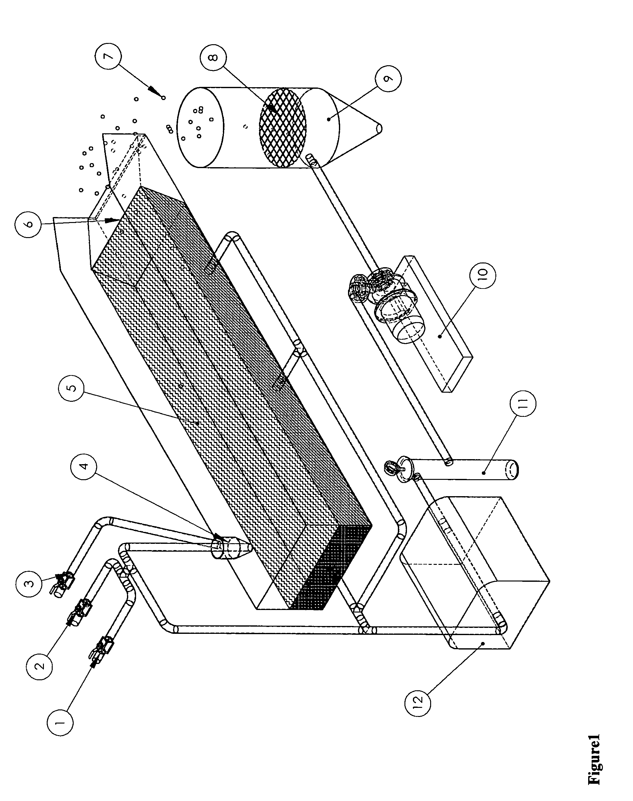
Sub-micron size silica aerogel particles were formed of toxic solvents at a very high temperatures and pressures and ability and is limited in the size of resulting beads.
Obtaining a narrow size distribution can be difficult in this process.
It is generally difficult to remove HMDSO inside the gel beads during the subsequent processing.
When gallons of gel beads continuously are produced in this bead making equipment, followed by the fast CO2 extraction process, the production footprint is diminished even further, resulting in increasing production capacity and potentially lowering production cost relative to other bead making methods.

Method used


Image

  • Methods for manufacture of aerogels
  • Methods for manufacture of aerogels
  • Methods for manufacture of aerogels

Examples


example 1

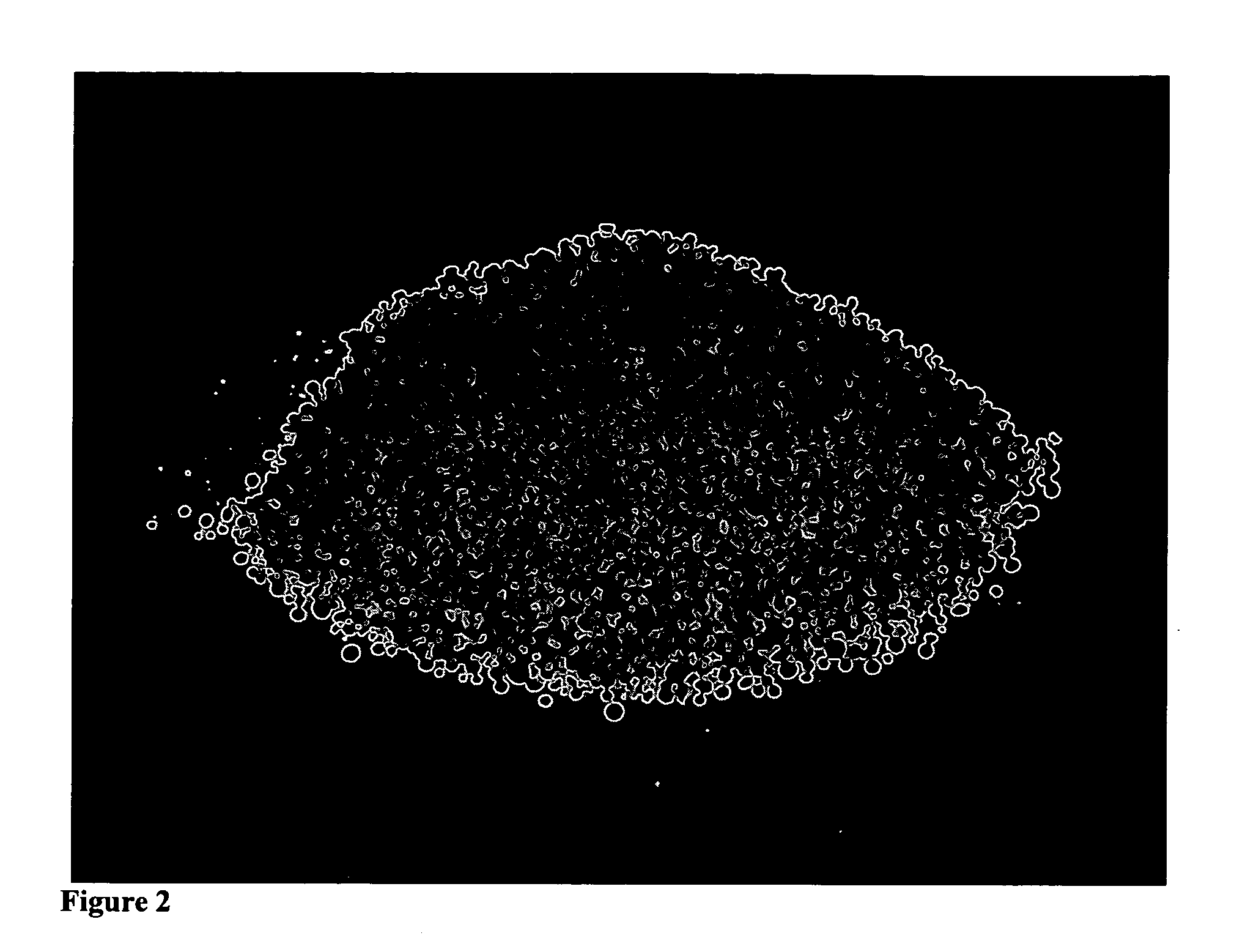
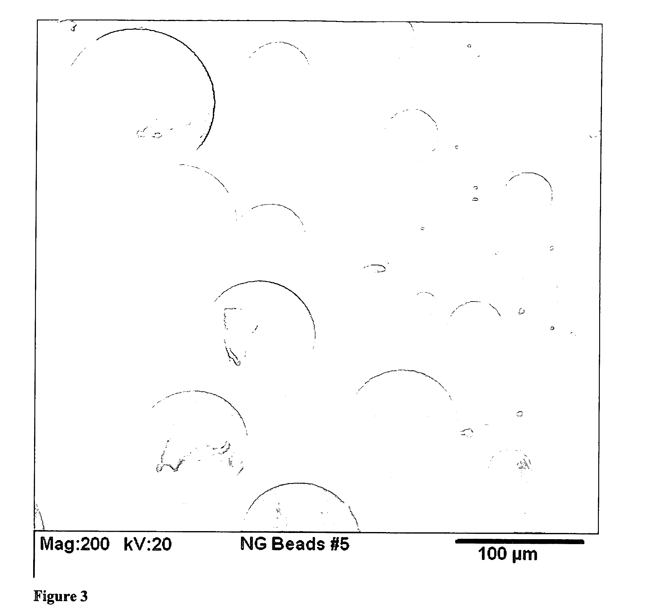
[0046] This example illustrates the formation of silica aerogel beads opacified with 5 weight percent loadings of carbon black. 7.07 kg of silica precursor was mixed with 9.78 kg ethanol and 1.57 kg for 1 hour at ambient conditions. It is then charged into a pressure container as a hydrolyzed sol. 6.75 kg of 28-30% aqueous base was mixed with 1.98 kg of ethanol and 130 Alcoblack® for 10 minutes. It is then charged into another pressure container as catalyst. The sol and catalyst were mixed together in a 2 to 1 ratio by a nozzle and dropped into the flowing silicone oil. A stream of compressed air was injected along the sol droplets, leading to a sol spray before entering the silicone oil. The resulting sol micro droplets flow slowly with the silicone oil toward the end of the vessel and downward into the collection bag. Collected beads can be removed periodically. After removing the excess amount of silicone oil, the bags of gel beads are sent through a silylation step and dried by ...

example 2

[0047] This example illustrates the formation of 1 to 3 mm size PMMA / silica aerogel beads with 15% loading of PMMA. 0.90 g of ter-butyl peroxy-2-ethyl hexanoate was added to a mixture of 40 g of MMA, 24.8 g of TMSPM and 18.3 g of methanol, following by vigorous stirring at 70 to 80° C. for 0.5 hr Trimethoxysilyl containing polymethacrylate oligomer was obtained as a viscous liquid in concentrated ethanol solution. 41.16 g trimethysilyl containing polymethacrylate oligomer was mixed with 829.6 g of Silica precursor, 207.9 g of ethanol, 93.8 g of water and 56.1 g of 0.1M aqueous HCl for 1 hour at ambient conditions. It is then charged into a pressure container as hydrolyzed sol. 34.7 g of 28-30% aqueous base was mixed with 261.3 g of ethanol and 330.7 g of water for 10 minutes. It is then charged into another pressure container as catalyst. The sol and catalyst were mixed together in a 2 to 1 ratio by a nozzle and dropped into the flowing silicone oil. The resulting sol droplets flow ...


PUM

PropertyMeasurementUnit
densityaaaaaaaaaa
densityaaaaaaaaaa
densityaaaaaaaaaa

Abstract

Embodiments of the present invention describe a method for producing gel beads comprising: depositing catalyzed sol droplets comprising a gel precursor into a moving dispensing medium, said medium being immiscible with the sol, and allowing gelation of the sol to occur in the moving dispensing medium thereby producing gel beads. This system utilizes a horizontally flowing dispensing medium where the catalyzed sol droplet is fully formed before deposited therein.

Description

PRIORITY [0001] This application claims priority from U.S. Provisional application Ser. No. 60 / 619,506 filed Oct. 15, 2004.GOVERNMENT INTEREST [0002] None [0003] Low-density aerogel materials (0.01-0.3 g / cc) are widely considered to be the best solid thermal insulators, better than the best rigid foams with thermal conductivities of 10 mW / m-K and below at 100° F. and atmospheric pressure. Aerogels function as thermal insulators primarily by minimizing conduction (low density, tortuous path for heat transfer through the solid nanostructure), convection (very small pore sizes minimize convection), and radiation (IR absorbing or scattering dopants are readily dispersed throughout the aerogel matrix). Depending on the formulation, they can function well at cryogenic temperatures to 550° C. and above. Aerogel materials also display many other interesting acoustic, optical, mechanical, and chemical properties that make them abundantly useful. [0004] The methods described in embodiments of...

Claims


Application Information

Patent Timeline
Patent Type & Authority Applications(United States)
IPC IPC(8): B01F3/12C01B33/12B32B3/26
CPCC01B33/1585C01B13/32Y10T428/249967
Inventor OU, DUAN LILEE, HAI CHINGGOULD, GEORGE L.TANG, YUE HUA
Owner ASPEN AEROGELS INC
Why Eureka
Try Eureka