Method of embedding tamper proof layers and

a technology embedding, which is applied in the field of embedding, can solve the problems of difficult work, inability to detect a tamper attempt done with insulated tools, and high cost of tamper proof layers as described abov

Active Publication Date: 2006-04-27
TWITTER INC
View PDF7 Cites 36 Cited by
  • Summary
  • Abstract
  • Description
  • Claims
  • Application Information

AI Technical Summary

Benefits of technology

[0016] One object of the invention to provide a method for manufacturi

Problems solved by technology

They are also made difficult to work with, for example due to intrinsic material/layer fragility when tampered (very low thickness, brittle layers, not solderable) such as to prevent shunting of the electrical circuit.
However, if the system described by reference to FIG. 1 is adapted to detect shorts created between conductive tracks 135 and 150 when using conductive drills or microprobes, it can not detect a tamper attempt done with insulated tools.
The tamper layers as described above are efficient but are very expensive and cumbersome to produce.
False calls during the manufacturing operations and in the field show the limits of the current solutio

Method used


Image

  • Method of embedding tamper proof layers and
  • Method of embedding tamper proof layers and
  • Method of embedding tamper proof layers and

Examples


Embodiment Construction

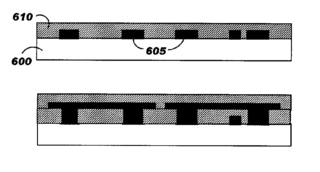
[0042] According to the invention a conductive ink, preferably a conductive polymeric ink, is placed into a precise pattern embedded into the module laminate stack-up construction.

[0043] In a preferred embodiment the printed circuit substrate is built in respect of symmetry to control mechanical behaviors like induce warpage from differential PCB materials shrinkage (metal, glass, plastic) because these thermo-mechanical strains and deformations are exacerbated when a non symmetrical construction is used. This problem is true also for recent developed technologies where layers are added on a rigid core, that can be a multilayer substrate, made of classical stack up of woven glass cloths impregnated with resins and copper sheets etched with circuit patterns. The reinforced or non-reinforced cores and may include an epoxy, polyester, cyanate ester, bismaleimide triazine, polyphenylene ether, annylated polyphenylene ether, polynorborene, liquid crystal polymer (LCP), Teflon, polyimide...


PUM

PropertyMeasurementUnit
Viscosityaaaaaaaaaa
Coloraaaaaaaaaa
Adhesion strengthaaaaaaaaaa

Abstract

A method for embedding tamper proof layers and discrete components into a printed circuit board stack-up is disclosed. According to this method, a plating mask is applied on a base substrate to cover partially one of its faces. Conductive ink is then spread on this face so as to fill the gap formed by the plating mask. To obtain a uniform distribution of the conductive ink and then gel it, the conductive ink is preferably heated. A dielectric layer is applied on the conductive ink layer and the polymerization process is ended to obtain a strong adhesion between these two layers. In a preferred embodiment, conductive tracks are simultaneously designed on the other face of the base substrate to reduce thermo-mechanical strains and deformations.

Description

FIELD OF THE INVENTION [0001] The present invention relates generally to electronic packages and to secure electronic packages and more specifically to a method of embedding tamper proof layers and discrete components into printed circuit board stack-up. BACKGROUND OF THE INVENTION [0002] According to the Department of Commerce of the United States of America, all secure cryptographic application are classified according to one of four possible levels listed in the technical specification untitled “Security requirements for cryptographic modules” published in the Federal Information Processing Standards FIPS PUB 140-2 by the national Institute of Standards and Technology (NIST). This standard specifies the security requirements that must be satisfied by a cryptographic module to be utilized within a security system, protecting sensitive but unclassified information. The standard provides four increasing qualitative levels of security that are intended to cover a wide range of potent...

Claims


Application Information

Patent Timeline
IPC IPC(8): H05K1/11H01R12/04
CPCH05K1/0275H05K1/095H05K1/167H05K3/108Y10T29/49155H05K3/28H05K2201/10151H05K2203/0568H05K3/1258
Inventor OGGIONI, STEFANO SERGIOCONDORELLI, VINCENZOHADZIC, NIHADGOTZE, KEVIN C.VISEGRADY, TAMAS
Owner TWITTER INC
Why Eureka
Try Eureka