System and method for nanoparticle and nanoagglomerate fluidization

a nanoparticle and fluidization technology, applied in the field of systems and methods/processes for fluidizing nanoparticles and nanoagglomerates, can solve the problems of difficult fluidization of nanoparticles, complex fluidization behavior of ultrafine particles, and geldart's classification of powders, etc., to achieve reliably and effectively fluidize a chamber or bed of nanoparticles, and facilitate substantially homogenous coating and/or treatment. , the effect of effective dispersion

Inactive Publication Date: 2006-04-27
NEW JERSEY INSTITUTE OF TECHNOLOGY
View PDF6 Cites 70 Cited by
  • Summary
  • Abstract
  • Description
  • Claims
  • Application Information

AI Technical Summary

Benefits of technology

[0023] According to the present disclosure, modification of an initial particle size distribution (e.g., an “as received” particle size distribution) to a desired particle size distribution range allows the disclosed fluidization system to achieve and maintain desired fluidization conditions. Through introduction of an external energy source and/or a pre-treatment step, as described in greater detail herein, the disclosed fluidization system advantageously establishes a state of dynamic equilibrium, wherein nanoagglomerates are formed, broken and randomly reformed, in an expanded fluidized bed. The dynamic equilibrium established according to the disclosed system/method offers many advantages, including facilitating substantially homogenous coating and/or treatment of nanoparticles/nanoagglomerates. Exemplary fluidization apparatus according to the present disclosure includes a gas supply source and at least one energy source for generating and supplying one or more of the energies disclosed herein, e.g., a vibrating source, a source for inducing a magnetic field, an acoustic source, and/or a source of centrifugal and/or rotational force. Other features that may be associated with the fluidization apparatus of the present disclosure include a gauge for measuring gas flow, a fluidization chamber, a distributor, gas dispersion elements (e.g., glass beads), filter(s), viewing device(s) and/or a vent.
[0024] According to the present disclosure, advantageous results are achieved in fluidizing nanoparticles and nanoagglomerates across a broad range of applications, e.g., applications that involve the manufacture of drugs, cosmetics, foods, plastics, catalysts, high-strength or corrosion resistant materials, energetic and bio materials, and in mechatronics and micro-electro-mechanical systems. More particularly, effective dispersion of nanoparticles and nanoagglomerates is achieved according to the present disclosure, thereby facilitating a host of nanoparticle-related processing regimens, e.g., mixing, transporting, surface property modifications (e.g., coating), and/or downstream processing to form nano-composites. In particular, by combining or coupling the flow of a fluidizing gas with one or more external forces, the combined effect is advantageously sufficient to reliably and effectively fluidize a chamber or bed of nanosized powders. That is, a bed may be expanded to more than double its original chamber or bed height with hardly any elutriation of the nanoparticles.
[0025] In addition, the system and method of the present disclosure advantageously provides for greater control of the fluidizing process, despite a high degree of mixing, thereby reducing powder loss relative to conventional fluidized chambers or beds. In one aspect of the present disclosure, for example, once the chamber or bed has been expanded, the supply of energy or force, e.g., vibration, may be terminated (or reduced) so that the chamber or

Problems solved by technology

However, the fluidization behavior of ultrafine particles, including nanoparticles which are in the extreme low end of Group C particles (<20 microns) in Geldart's Classification of Powders, is much more complex and has received relatively little attention in the literature.
Nanoparticles are difficult to fluidize due to their strong interparticle forces.
As far as is known, fluidization of nanoparticles (which are three orders of magnitude smaller than traditional group C powders) has heretofore been extremely difficult, if not impossible, to effectively achieve.
However, there tends to be significant powder loss and non-uniform fluidization behavior.
In addition, large agglomerates can form near the distributor.
For other nanoparticles, fluidization results in a very limited bed expansion, and large bubbles rise up very quickly through the bed.
However, even for the homogeneously fluidized nanoparticles, relatively large powder elutriation occurs at the high gas velocities required to fluidize the nanoagglomerates.
This loss of particles may hinder

Method used


Image

  • System and method for nanoparticle and nanoagglomerate fluidization
  • System and method for nanoparticle and nanoagglomerate fluidization
  • System and method for nanoparticle and nanoagglomerate fluidization

Examples


example 1

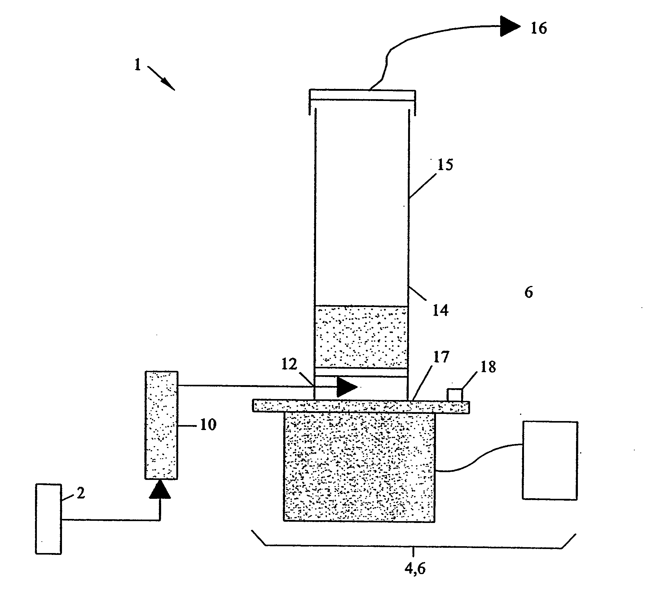
[0190] An apparatus as shown in FIG. 2 was used to fluidize nanopowders using any gas such as air or nitrogen and vibration.

[0191]FIG. 36 shows an exemplary plot of observed pressure drop and bed expansion vs. superficial air velocity. At gas velocities greater than 0.1 cm / sec and a vertical sinusoidal vibration of 5.5 g's, the bed begins to expand and continues to expand both before and after the minimum fluidization velocity, defined as the velocity at which the pressure drop across the bed is equal to the weight of the bed divided by its cross sectional area. The bed expanded to four times its initial height and appeared to be uniformly fluidized with negligible elutriation.

example 2

[0192] Using the apparatus of FIG. 2, and 12 nm silica powders with a constant flow rate and vibrational parameters of 50 Hz and 2 g's, the silica powders were fluidized.

[0193] FIGS. 37(a) and 37(b) illustratively show what may typically occur during a fluidization process. With air or vibration alone, nothing useful occurs to a conventional nanoparticle powder bed. When the two are coupled together, however, the nanoparticle size distribution is reduced / lowered and the powder bed expands with vigorous particle movement.

example 3

[0194] Using the apparatus of FIG. 2, and 12 nm silica, tracer silica dyed with methylene blue and constant flow rate of dry air and vibrational parameters of 50 Hz and 4 g's, was fluidized.

[0195]FIG. 38 shows the progression of mixing 12 nm silica with a small amount of the same nano-sized silica dyed with methylene blue. The bed was operated at a constant air velocity of 0.45 cm / see with a vertical sinusoidal vibration of 4 g's at a frequency of 50 Hz. As can be seen in the figure, as soon as the vibration was turned on the bed started to expand and uniform bubble less fluidization was observed. Within 2 minutes, the entire bed turned blue, indicating not only good fluidization, but also very good mixing.


PUM


Abstract

With the coupling of an external field and aeration (or a flow of another gas), nanoparticles can be smoothly and vigorously fluidized. Multiple external fields and/or pre-treatment may be employed with the fluidizing gas: sieving, magnetic assistance, vibration, acoustic/sound or rotational/centrifugal forces. Any of these forces, either alone or in combination, when coupled with a fluidizing medium, provide excellent means for achieving homogenous nanofluidization. The additional force(s) help to break channels as well as provide enough energy to disrupt the strong interparticle forces, thereby establishing an advantageous agglomerate size distribution. Enhanced fluidization is reflected by at least one of the following performance-related attributes: reduced levels of bubbles within the fluidized system, reduced gas bypass relative to the fluidized bed, smooth fluidization behavior, reduced elutriation, a high level of bed expansion, reduced gas velocity levels to achieve desired fluidization performance, and/or enhanced control of agglomerate size/distribution. The fluidized nanoparticles may be coated, surface-treated and/or surface-modified in the fluidized state. In addition, the fluidized nanoparticles may participate in a reaction, either as a reactant or a catalyst, while in the fluidized state.

Description

CROSS-REFERENCE TO RELATED APPLICATION [0001] The present application claims the benefit of the following co-pending, commonly assigned provisional patent applications: (i) “Vibrofluidization and Magnetically Assisted Fluidization of Nanoparticles,” filed on Jul. 29, 2003 and assigned Ser. No. 60 / 490,912, and (ii) “Nanoparticle and Nanoagglomerate Fluidization System and Method,” filed on May 4, 2004 and assigned Ser. No. 60 / 568,131. The contents of each of the foregoing provisional patent applications are incorporated herein by reference.BACKGROUND OF THE DISCLOSURE [0002] 1. Technical Field [0003] The present disclosure relates to system(s) and method(s) / process(es) for fluidizing nanoparticles and nanoagglomerates. More particularly, the present disclosure is directed to systems and methods / processes for fluidizing nanoparticles and nanoagglomerates utilizing a fluidizing gas with one or more external forces, e.g., a vibration force, a magnetic force, an acoustic force, a rotatio...

Claims


Application Information

Patent Timeline
IPC IPC(8): B02C19/06B01F33/40B01J8/24B01J8/40B01J8/42B01J19/10H01M
CPCB01F11/0266B01F13/0255B01F13/0809B01J8/1872B01J8/40B01J8/42B01J19/10B01J2208/00681B82Y15/00B01F31/86B01F33/406B01F33/451
Inventor PFEFFER, ROBERTNAM, CAROLINE H.DAVE, RAJESH N.LIU, GUANGLIANGQUEVEDO, JOSE A.YU, QUNZHU, CHAO
Owner NEW JERSEY INSTITUTE OF TECHNOLOGY
Why Eureka
Try Eureka